Previously shared CCS C sample application circuit code archive (C and Hex Isis) is a large archive with all source codes and proteus simulation circuits such as CCS C projects shared in the font…. Electronics Projects, CCS C Applications Proteus Simlations “microchip projects, microcontroller projects, pic16f876 projects, pic16f877 projects, pic18f2550 projects, pwm circuits, “
Previously shared CCS C sample application circuit code archive (C and Hex Isis) is a large archive with all source codes and proteus simulation circuits such as CCS C projects shared in the font.
In a majority of CCS C projects, pic16f876 and pic16f877 microcontrollers are used. In projects with USB communication, pic18f4520 pic18F4550 is used.
CCS C PROJECT LIST
T3.E1: Turn on a LED with a switch.
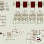
T3.E2: Decimal counter from 0 to 99 with 7 segments.
T3.E3: To control a menu on the LCD with two push buttons.
T3.E4: Displaying the status of a port entry via a graphical display
T3.E5: Displaying data of 3×4 matrix keyboard on LCD.
T3.E6: Access control with keyboard.
T3.E7: Control the speed of a DC motor with the keyboard.
T4.E1: Opening and closing the Led with external cut.
T4.E2: 1 KHz signal generation via TMR0.
T4.E3: 1 second delay generation via TMR1.
T4.E4. Measuring pulse width using TMR1 and external cut.
T4.E5: Generating a 1 KHz signal via TMR2.
T4.E6: Control the speed of a DC motor with the keyboard. Using TMR1. Digital tachometer
T4.E7: Multi-function with one key.
T5.E1: Reading a voltage from channel AN0.
T5.E2: Thermometer with NTC.
T5.E3: NTC and pressure sensor barometer / Altimeter.
T5.E4: Acquisition of negative tensions.
T6.E1: Measurement of a pulse width using the CCP module.
T6.E2: Generating a 2 KHz signal via the CCP module.
T6.E3: Conversion of AD to CCP module. Producing a PWM signal proportional to the measured signal.
T6.E4. Basic oscilloscope with CCP module and graphical display.
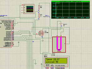
T6.E5: PID control of oven temperature.
T6.E6: Problems in the PWM simulation of the CCP module.
T7.E1: PIC serial communication
T7.E2: Serial communication from PIC to PC.
T7.E3: PC communication to the PIC (two-way).
T7.E4. An I2C series EEPROM write / read.
T7.E5: Reading the I2C temperature sensor, an I2C real-time clock for storage of your data in the I2C series EEPROM. Read EEPROM data via serial port.
T8.E1: Real-time clock with PIC18F4520.
T8.E2: Self-regulating voltage amplifier with PIC18F4520.
T9.E1: PID control of an oven temperature with RTOS. More visualization control. Check more screens and programming with the PIC18F4520.
T10.E1: CDC USB.
T10.E2: CDC USB.
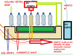
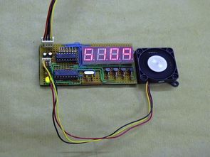
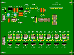
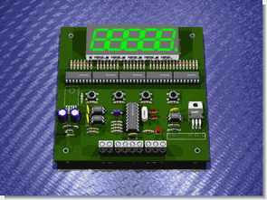
SAMPLE PROTEUS CIRCUIT DIAGRAMS
Image may be NSFW.
Clik here to view.
Image may be NSFW.
Clik here to view. Image may be NSFW.
Clik here to view. Image may be NSFW.
Clik here to view.
Source: CCS C APPLICATIONS PROTEUS SIMLATIONS
Alternative File Download LINK list (in TXT format): LINKS-25948.zip
- Image may be NSFW.
Clik here to view.![Share via Facebook]()
- Image may be NSFW.
Clik here to view.![Share via Google]()
- Image may be NSFW.
Clik here to view.![Share via Twitter]()
- Image may be NSFW.
Clik here to view.![Share via LinkedIn]()
- Image may be NSFW.
Clik here to view.![Share via WhatsApp]()
- Image may be NSFW.
Clik here to view.![Share via Pinterest]()
- Image may be NSFW.
Clik here to view.![Share via VK]()
- Image may be NSFW.
Clik here to view.![Share via Tumblr]()
- Image may be NSFW.
Clik here to view.![Share via Xing]()
- Image may be NSFW.
Clik here to view.![Share via Ravelry]()
- Image may be NSFW.
Clik here to view.![Share via StumbleUpon]()
- Image may be NSFW.
Clik here to view.![Share via Reddit]()
- Image may be NSFW.
Clik here to view.![Share via Email]()
- Image may be NSFW.
Clik here to view.![Share via Digg]()


The post CCS C APPLICATIONS PROTEUS SIMLATIONS appeared first on PIC Microcontroller.