Quantcast
Viewing all 223 articles
Browse latest View live

How to get started with PICAXE 08M microcontroller

This is instructable for how to get started with PICAXE 08M microcontroller.
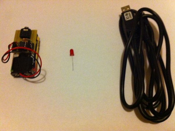
To get started, you need:
– 08M Protoboard or same kind of board (Can be homemade)
– A LED
– AXE027 USB Cable
– 3V Power supply

Image may be NSFW.
Clik here to view.
How to get started with PICAXE 08M microcontroller
Step 1: Connect the led to pin 4

Just  connect cathode lead to Ground, and anode lead to pin 4 of the microcontroller like this

Step 2: Connect the power and the cable

Connect the power, and plug the cable to the socket.
Then open PICAXE Programming Editor.
If you don’t have it, download it from http://picaxe.com/

Step 3: Write the code and press “Program”

Write this code to the editor:
main:
high 4 ‘LED on
pause 1000 ‘Pause 1 second
low 4 ‘LED off
pause 1000 ‘Pause 1 second
goto main ‘Repeat
Then press the “Program” button on the top.

Image may be NSFW.
Clik here to view.
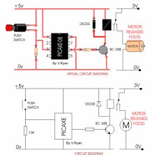
How to get started with PICAXE 08M microcontroller Schematic

Step 4: Watch your LED blinking!

It is ready now, good luck for future!
Links:
PICAXE Downloads – http://www.picaxe.com/Software
PICAXE Manuals – http://www.picaxe.com/Manuals
PICAXE Shop – http://www.techsupplies.co.uk/PICAXE
All the links you need to order, download, and study PICAXE!
Hope you enjoyed! Image may be NSFW.
Clik here to view.
:)


For more detail: How to get started with PICAXE 08M microcontroller

The post How to get started with PICAXE 08M microcontroller appeared first on PIC Microcontroller.


Breathalyzer circuit using 8051


Alcohol Breathalyzer circuit using 8051 microcontroller (AT89S51).

This article is about a breathalyzer circuit using 8051 microcontroller which outputs the blood alcohol content (BAC) from the breath. The BAC is displayed in percentage on a 3 digit seven segment display. The microcontroller used if AT89S51 which belongs to the 8051 family and the alcohol sensor is MQ135 gas sensor from Futurelec.Image may be NSFW.
Clik here to view.
Breathalyzer circuit using 8051

MQ135 gas sensor.

MQ135 is a stable and sensitive gas sensor which can detect  ammonia, carbon dioxide, alcohol, smoke, nitrogen dioxide etc. The sensor consists of a tin dioxide sensitive layer inside aluminium oxide micro tubes, measuring electrode and a heating element inside a tubular aluminium casing. The front end of the sensor is covered using a stainless steel net and  the rear side holds the connection terminals.

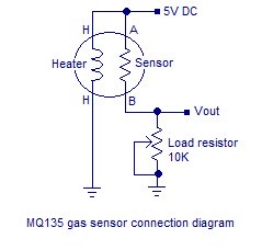
The ethyl alcohol present in the breath is oxidized into acetic acid while passing over the heating element. This ethyl alcohol falls on the  tin dioxide sensing layer and as a result its resistance decreases. This resistance variation  is converted into a suitable voltage variation using an external load resistor. The typical connection arrangement of an MQ135 alcohol sensor is shown below.

MQ135 has different resistance values at different temperature and different concentration of gases. The manufacturer recommends to calibrate the sensor at 100ppm of ammonia or 50ppm of alcohol. The recommended value of the load resistor is between 10K to 47K.

The voltage output of the alcohol sensor is converted into a digital format using the ADC0804 (IC1). The Vref/2 pin of the ADC is held at 1.28V using the voltage divider network made of R14 and R15. Vref/2 =1.28V means the step size of the ADC will be 10mV and the output of the ADC will increment by one bit for every 10mV increment in the analog input. Refer the datasheet of ADC0804 for a better grasp. Digital out of the ADC (D0 to D7)  is interfaced to Port1 of the microcontroller. Control signals CS, RD, WR, INTR are obtained from the microcontrollers P3.7, P3.6, P3.5, P3.4 pins respectively. R9 and C1 are associated with the clock circuitry of the ADC0804.

Capacitor C3 connected between Vin+ and Vin- of the ADC0804 filters of noise (if any) in the sensor output. If C3 is not used the digital output of the ADC will not be stable. This filter capacitor will surely induce some lag in the ADC response but it is not very relevant in this entry level application. The microcontroller performs required manipulations on the ADC digital output in order to convert it into BAC % and displays it on the three digit seven segment display. Port0 of the microcontroller is interfaced to the multiplexed three digit seven segment display. The drive signals for the threes digits are obtained from the microcontroller’s P3.0, P3.1, P3.2 pins respectively.Image may be NSFW.
Clik here to view.
Breathalyzer circuit using 8051 schematic

Program.

ORG 00H
MOV P1,#11111111B
MOV P0,#00000000B
MOV P3,#00000000B
MOV DPTR,#LUT
MAIN: MOV R4,#250D
      CLR P3.7
      SETB P3.6
      CLR P3.5
      SETB P3.5
WAIT: JB P3.4,WAIT
      CLR P3.7
      CLR P3.6
      MOV A,P1
      MOV R5,A
      SUBB A,#86
      JC NEXT
      SETB P3.3
      CLR PSW.7
NEXT: MOV A,R5
      SUBB A,#115D
      JNC LABEL
      MOV A,#00000000B
      CLR PSW.7
LABEL: MOV B,#5D


Notes.

  • The MQ135 gas sensor requires around 5 minutes of preheat before the first use.
  • The MQ135 takes few minutes to retrace back to its normal condition after a positive test (alcohol present in the breath).
  • If there is no alcohol in the breath  the sensor output will swing back to its normal condition very fast.
  • Read these articles Interfacing seven segment display to 8051 microcontroller , Interfacing ADC to 8051 microcontroller  before attempting this project.
  • This breathalyzer circuit is just an entry level one and is not suitable for high end applications such as law enforcement or laboratory application.
  • The logic for converting the digital output of ADC into BAC percentage was obtained using approximation techniques.

For more detail: Breathalyzer circuit using 8051

The post Breathalyzer circuit using 8051 appeared first on PIC Microcontroller.

Gas Cooker & Water Purifier Using Free Energy

I originally wrote this for my final year project in 2005. I won’t provide a parts list as certain technology has moved on such as the ease of Arduino for the electronics and solar cells are a lot better and readily available now. Also I was a student at the time and so my budget was extremely limited but even today I am happy with my design.

Many parts of the world suffer from lack of clean water to drink and heat to cook their food and get by from day to day. This instructable is designed to try and provide a cheap means of providing clean water and heat to cook with for a very low price tag.

Hydrogen is very easily made by using electrolysis which can be driven from green technologies such as wind and solar power. Electrolysis will work with stagnant or dirty water to provide Hydrogen and Oxygen gas. This gas mixture is highly combustible and as such makes a great fuel source. The added benefit is that burning hydrogen and oxygen produces 100% pure water.

There are probably lots of flaws with this design and essentially what you are making can be very dangerous if left powered and unattended so please be advised. I’ve since been employed in the embedded industry for over 8 years and have learnt a massive amount so please if you have any questions (about electronics / microcontrollers / Arduino) then let me know. Anyway I hope you enjoy reading my instructable as much as I enjoyed designing and building it. I do intend to dig this project out the loft and take a video of it in action. Yes it’s still working after all this time.

Please read on to find out more….Image may be NSFW.
Clik here to view.
Gas Cooker & Water Purifier Using Free Energy

Step 1: Alternative energy and the hydrogen industry

Well researched methods such as solar, wind or water power are fantastic in that they use the energy present in nature and convert that energy into electricity. So ok with these methods we have electricity being produced so now we need a method to use this electricity in our current technology. This is where electrolysis comes into the picture. Electrolysis was discovered in 1800 by an English man named William Nicholson. The reaction that occurs during electrolysis is simple, two electrodes are placed in parallel and submerged in a liquid, the electrodes can be made of stainless steel, aluminum or any other metal as long as it doesn’t react with the liquid and has a high surface conductivity. When an electrical potential is placed between the electrodes in water the only path the current can flow is via the impurities in the water. At the electrodes electrons pass through the water from the cathode to the anode creating concentrations of oxygen and hydrogen at the anode and cathode respectively.

Electrolysis may seem a simple and useless process to use for energy but when used on water a very unique reaction occurs, where there was a hydrogen oxide molecule there becomes two hydrogen molecules and a oxygen molecule (see Fig 2). As both of these new substances are gasses at room temperature they collect into bubbles and rise to the surface of the water as a mixture. This mixture then makes a readily available fuel source that can be used in an engine, cooker, boat, automobile, airplane, heating e.g. all of the products that run on fossil fuels today such as petrol or coal. One drawback to hydrolysis is when using salt water as this produces chlorine gas which is very harmful. This side effect can be easily avoided by removing any salt content through evaporating the water first. In this project tap water will be used as the means of fuel storage so this problem will not apply.

Since the discovery in 1800 and first documentation in 1832 by Michael Faraday, hydrolysis has been used multiple times to try to produce a new form of energy. However none of the products made have ever been very useful due to problems such as lack of efficiency and speed of gas production. Recently though hydrogen technology and electrolysis has come back into the lime light as the fossil fuel industry starts to collapse. Honda’s newest car for example employs a high pressure tank of hydrogen to power in its fuel cells to power the car.

Unfortunately one of the electrolysis researchers called William Rhodes claimed the invention for himself and named the output gas ‘Browns gas’. He claimed to get more energy out of the hydrogen then was put into the water to create it in the first place. This is obviously against the laws of physics and thermodynamics but still he used his rouse to extort a great deal of money, claiming it was for further research. He then disappeared with the money and was never heard from again however his inventions (scams) still live on.

Another Recent development that has helped the start of the hydrogen industry was the fairly new discovery of hydrogen fuel cells (see Fig 3). These are constructed from two chambers to hold hydrogen and oxygen with a PEM (Proton Exchange Membrane or Polymer Electrolyte Membrane) separating the gasses. When hydrogen and oxygen are present on either side of the material a current is generated, water and heat are given off. However there are difficulties with this technology as when the fuel cell is running one side of the PEM tries to dry out and will crack if not kept wet, the other side needs to be dry to conduct the current and is producing water. This makes it difficult to get the fuel cell to work at all or for any sustained period so it will not be included in the project as the budget and technology is limited.

here is however hope for the hydrogen industry in sight, a company in Australia seem to have got it right, producing goods such as water fueled generators, fuel cells, electrolysis chambers, hydrogen boilers etc, proving that if used correctly hydrogen can be a very useful and versatile fuel medium.

With all this information in mind a project was chosen to demonstrate this remarkable technology and the benefits that it would bring to the fuel and power industries. The aim of the project is to make a cooker to demonstrate how simple it is to manufacture the hydrogen and oxygen fuel mixture locally on site and as needed to prevent the need for storing excess. To demonstrate this technique and test its efficiency the project is going to be based on a hydrogen cooker with gas being produced locally in a sealed pressurized chamber. Figure 4 on the left shows this said system with a device between the input gas chamber and the output hob. This device allows combustion to be quenched if it manages to travel up the fuel pipe before it manages to reach the hydrogen production chamber.

(Fig 5) is a picture of the first electrodes that was constructed to test the feasibility of the output gas as a fuel source. The electrodes were made by sanding down a steel can and shaping a steel metal plate around a bottle so it would fit around the can. Wire was then threaded around the can to insulate it from the metal sheet and act as a spacer to keep the distance between the plates constant. Using a 12 volt battery connected to the anode and cathode of my electrodes I submerged the device in tap water and waited for a result. The output was almost immediate and to my surprise the whole surface area of the steel plates was covered in bubbles of gas given off from the process.

To provide power for my hydrogen cooker system it was decided that green energy should be used because if the system was just plugged into the mains then the process would be running mainly on fossil fuels and would defeat the purpose of this clean recyclable energy. The green energy chosen to power the cooker was primarily solar as this is a well established technology and it is generally always light for some time every day (see Fig 7). A second green energy was then included to complement the solar power and help to keep a trickle of charge running to the battery. This was chosen to be wind power as wind is present all day and night and it is also easy to implement with a simple motor and spinner assembly (see Fig 6).

Step 2: Design Concepts

The cooker system will be constructed as shown in Fig 8. It will consist of a solar cell and a wind turbine powering a rechargeable battery through a regulator. The battery will then power a microchip microcontroller connected to a L.C.D screen and the chamber electrodes. The production chamber will also be monitored by the microcontroller by means of water level, hydrogen pressure and temperature sensors. The sensors outputs will be displayed on the L.C.D and hydrogen production will be shut off after a certain pressure (around 5psi) to ensure safety.

(Fig 9) The first chamber made and designed to produce the hydrogen for the project. After construction it was ascertained that although the chamber was water tight and pressure tight, it probably wouldn’t be very hydrogen tight. Therefore another technique was employed to manufacture the production chamber. Instead of trying to make the whole chamber, bought components with seals would be obtained and used instead to guarantee hydrogen would not escape at least short term.

After shopping around looking for the strongest and best sealed container, it was decided to use a heavy duty straight drain pipe connector and two heavy duty drain pipe end caps. These were chosen because they were strong and resilient and also came with a perfect seal ideal for trapping in hydrogen. These drain pipe pieces are to be connected into the designed system by means of using polycarbonate squares to grip the ends of the two caps (see Fig 10). The polycarbonate will then be squeezed together using strips of threaded metal studding. The controller electronics will then be attached to this studding and encapsulated inside a box to prevent any unwanted sparks getting near to the hydrogen.

With the hydrogen and oxygen mix being produced there will have to be measures put in place to ensure the safety of surrounding population. The worst thing that could happen is if a flame or spark got into the production chamber and came into contact with the pressurized gas. Using a fish tank bubbler submerged in a separate water tank (Fig 11), there is no way for a combustion to travel from the hob to the production chamber.

Rather then a propane or butane cooker which needs a large quench gap, primary and secondary air mixing to burn correctly, hydrogen needs a much smaller quench gap to prevent the combustion reaching the inside of the gas pipe. Also unlike propane or butane, hydrogen cannot have primary or secondary air mixing as oxygen is already inside the mixture. As the gas travels though this quench gap there is a maximum amount that can travel though the hole at any time. Therefore the bigger the quench gap is, the more gas that can come through, making it easier for the combustion to travel back through and along the stream of gas. For hydrogen this small quench gap (Approx 1mm) keeps the system from rapidly loosing pressure and also to help prevent the combustion reaction from traveling back past the gap and further up the pipe. (Fig 12) shows a hydrogen burner with steel wool covering the quench gaps in the piping. This steel wool is useful as it firstly reduces the temperature of the burning hydrogen by limiting the surrounding oxygen from reaching the reaction, and secondly useful by acting like a catalyst. Once the gas is ignited the wool will get heated up and then act to combust any further gas as it flows through helping to create a steady output temperature.

Step 3: The Electrodes

Firstly a second experiment was done by using several aluminum plates and separating them with various insulators to vary the width between the plates (see Fig 13). Each time the width of the insulator between electrodes was altered; the electrodes were clamped together, submerged into tap water and a current was applied. Estimated output was decided on disturbance of water, quantity and size of gas bubbles. After testing lots of insulating sizes and recording the findings, the best result was when the plates were around 1mm apart.

Now that a suitable insulating gap had been found more plates were added to maximize conductivity and spacers were glued to each plate in every corner (see Fig 14). The plates were then held together by means of two pieces of strong pieces of elastic. Each plate was tested for connectivity to its wire and that no connection was present to its surrounding plates.

The wires were then cut to size and secured in place by the elastic (see Fig 15). Bits of the plastic insulation from some mains cable was used to separate the places were the cables touch the electrodes to guarantee that none of them would touch their neighbor.

The finished electrodes were then placed in the bottom of the chamber (Heavy duty drain pipe end piece). Pieces of heavy duty plastic were cut into shape and used to wedge the electrodes in place in the chamber bottom. The whole setup was then glued and allowed time to set (see Fig 16). Conductivity between the electrodes was then rechecked for safety reasons.

Step 4: Bubbler Chamber

Shown here is a fish tank bubbler stone attached to a plumbing end piece (see Fig 17). A hole was drilled in the end cap to allow the hose from the bubbler stone to be pushed through and glued in place. Epoxy resin was used to hold the bubbler stone in place and help seal in the hydrogen.

The finished bubbler chamber with bubbler stone sealed inside is now ready to filter the hydrogen output in order to prevent a combustion reaction from ever reaching the hydrogen production chamber (see Fig 18). Hole drilled in another end cap and a stainless steel pipe fitting was glued in place to allow for the incoming hydrogen gas to get out again and be piped to the hob.Image may be NSFW.
Clik here to view.
Gas Cooker & Water Purifier Using Free Energy schematic

Step 5: Pressure Chamber

With the production chamber partially completed it was time to test the output from the electrodes. The chamber was partially sealed to contain the produced hydrogen and oxygen gas and then a filled with tap water for the chemical reaction to occur. A 12 volt potential from a small lead acid battery was then applied across the anode and cathode of the electrodes. Output gas from the chamber was piped into a container of water and allowed to bubble into an upside down submerged container (see Fig 19). A stop watch was then started to measure how long it took the electrodes to produce 250ml of the hydrogen and oxygen mix. After only 11 minutes of producing gas the 250ml level was reached and the electrodes were then deactivated. The hydrogen and oxygen was then tested for its purity by raising the container up out of the water at the same time as inserting a lit splint into the gas. (Warning… I don’t advise you do this unless you know what your doing!!!). A rather loud ‘pop’ came from the mixture as it combusted proving that there was indeed hydrogen and oxygen present in a substantial enough level to provide power for a device. The bubbler chamber was not needed for this test as currently no hydrogen or oxygen is being held and allowed to build up anywhere to any hazardous (explosive!!!) pressure.

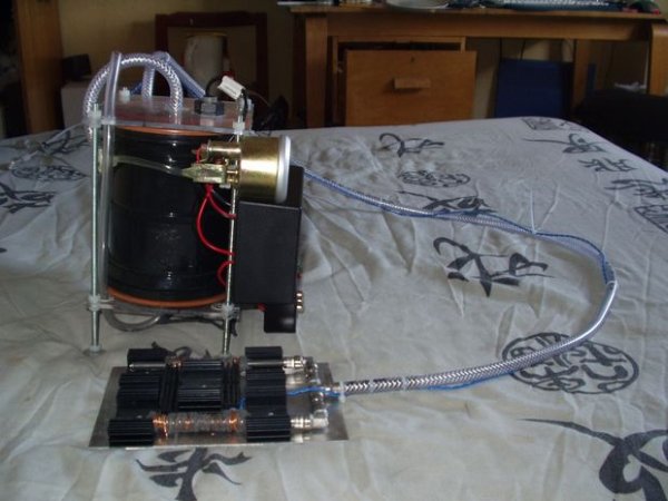
(Fig 20) is the completed hydrogen production chamber with analogue safety pressure gauge attached. This extra gauge is needed to a: verify the digital input pressure and b: act as a backup if the microcontroller fails or hangs. Also shown on the right of the chamber is the release valve used to control the flow of the output hydrogen and oxygen.


For more detail: Gas Cooker & Water Purifier Using Free Energy 

The post Gas Cooker & Water Purifier Using Free Energy appeared first on PIC Microcontroller.

Steam Turret Tank R/C PIC Servo Controller

A Microchip PIC based servo controller offering many of the capabilities of digital servos for under $9!

The controllers capture the r/c receiver output, optionally manipulate the samples, then regenerate new servo control signals. As such, they greatly enhance what is possible with cheap servos. They were created for my Steam Turret Tank Instructable.

Here is a list of some of the things possible:

  • Expand number of things that can be controlled.
  • Drive multiple servos (with different ranges) from single input.
  • Limit, increase or reverse range of motion on servos.
  • Change center point on servo.
  • Convert absolute servo position to delta/incremental changes.
  • Convert transmitter actions into on/off toggles (for lighting effects, etc…)
  • Suppress servo control pulses when static to reduce chattering.
  • Encode r/c positions into serial bitstream for a remote controller.

It’s programmed using a Microchip 5-pin ICSP (In-Circuit Serial Programming) header. You’ll need to install MicroChip’s free MPLAB-X – there are versions for Windows, Linux & Mac. You’ll also need a device programmer, such as Microchip’s PICkit-3.Image may be NSFW.
Clik here to view.
Steam Turret Tank R C PIC Servo Controller

Step 1: Tools Required

The tools needed are pretty minimal. A soldering iron & solder obviously. Extra liquid flux can be helpful, especially for easily removing solder bridges. Needle pliers for placing parts, and wire cutters for trimming leads.

For programming the PIC microcontroller once the board is assembled, you need a PicKit-3 or equivalent.

Step 2: Bill of Materials

Base Circuit

Qty	Description			Price*		Mouser Part#
(1)	PCB(from OSHPark) 		$2.35/ea	n/a
(1)	PIC16LF1825 14-SOIC		$1.60/ea	579-PIC16LF1825-I/ST
(1)	3.3V voltage regulator		$0.38/ea	579-TC1015-3.3VCT713
(1)	47uf 1210 16V capacitor		$0.74/ea	81-GRM32EC81C476KE5L
(1)	1uf 0805 16V capacitor		$0.06/ea	77-VJ0805V105ZXJCBC
(1)	470pf 0805 50V capacitor	$0.06/ea	77-VJ0805Y471JXAPBC
(1)	1N4148 Diode (300ma)		$0.06/ea	512-1N4148TR
(3)	6 pin female headers		$2.13/qty3	517-929870-01-06-RA
(3)	6 pin headers (gold plated)	$0.87/qty3	649-67996-206HLF
(1)	5 pin header for ICSP		$0.19/ea	538-42375-1247
(1)	2 pin r/a header for power	$0.26/ea	571-826631-2
					$8.70/total

Optional external transistors:

(1)	SOT23 NPN Transistor		$0.13/ea	771-BC846215
(1)	100 ohm 0805 resistor		$0.10/ea	754-RR1220P-101D

Optional SPI ROM:

(1)	128KBit SPI Bus EEPROM		$1.01/ea	579-25AA128-I/SN

* Prices as of 8/25/2014

Step 3: Servo Control Signals

Servos use a three wire connection: ground, power, and the control signal. For the most part, all vendors use that ordering also (Futaba/JR/Hitec/Airtronics-Z). Old Airtronics servos are an exception (swapped power/ground).

The control pins use pulse-width-modulated signals. Pulses varying in width that repeat periodically. The pulses typically range from 1 to 2msecs and repeat every 20msecs. If the pulses stop, the servo stops at its last position.

A 1msec pulse makes a servo moves to one end of its range. A 2msec pulse, and it goes to the other. A pulse somewhere in between moves the servo accordingly. There are no standards however and some servos move more or less amounts.

Some servos are sold as “digital”. They accept the same type of control signals. However, digital flavors use a microcontroller instead of an analog control loop on the servo motor. They can move faster & be programmed to manipulate the ranges/center-points/reverse-range/constant-run/etc… The down side is higher price, more power consumption & more noise.

Now for under $9 you can reuse older servos & get many of those same features.

Step 4: Receiver Outputs

I’ve only looked at the output of a couple different brands of standard r/c receiver, but both worked the same. ie: sequential/stepped outputs.

The receivers do not pulse all their control outputs at once. The first channel pulses (ie: 1msec to 2msec). After the first pulse deasserts, then the second channel pulses. Repeat for remaining channels.

From the PIC programming perspective, sequential outputs make life easier.

A tighter software loop can be used, meaning larger counts & better resolution. For example, sampling a pulse 100 times instead of 20 times. The former gives five times the resolution – a good thing!

To verify your receiver works the same, use an oscilloscope or logic analyzer. Look at a couple different receiver control signal pins. If they resemble the drawing you’re good to go.

Step 5: Multiple Controllers

My steam turret tank has two servo controllers. One in the tank chassis base attached to the receiver, and another in the turret itself.

The base-controller samples the receiver and drives the engine servos, steam whistle servo & head/tail lights. It also supplies a serial bitstream (of the raw receiver inputs) to the turret-controller.

The turret-controller receives the serial bitstream, and drives the turret servo, cabin light, gun elevation servo, gun light, gun solenoid, and the turret WTV020-SD sound module. The latter three all trigger simultaneously but for different amounts of time.

Step 6: Software Flow

The code is written in Microchip assembly language (mpasm). Instead of plowing through gory detail I’ll give a hopefully easier to understand overview.

The servo controller software samples the inputs, averages the last few to filter noise, performs range/center-point adjustment, and then regenerates the outputs (optionally suppressing inactive ports).

There are two variants of the code. The only real difference is where the servo inputs come from. The base controller directly samples the receiver. The turret samples a serial bitstream generated by the base.

The same source code supports both variants. See defines TXCHIP (for base) & RXCHIP (for turret version).

Various options have associated timer counts. The code implements timers by tracking the number 20msec loops. For example, if an input has been idle for 32 loops (0.64 sec) the idle input filter will trip.Image may be NSFW.
Clik here to view.
Steam Turret Tank R C PIC Servo Controller schematic

Step 7: Configuring R/C Adapter

There are numerous configuration options available in the source code. The defines select different features, specify servo ranges, change center points, select pulse suppression, etc… Currently these are all compile time decisions.

The PIC16LF1825 does have EEPROM memory, which can be dynamically updated. Making a run-time adjustable version is on my TO-DO list, to support updating ranges/modes on the fly instead of recompiling every tweak.

Here are brief descriptions of the current options:

TXSERIAL

  • Generate serial bitstream on output1 (port A, bit0). Used on tank base controller.

RXSERIAL

  • Sample input 0 (port A, bit 5) for serial bitstream instead of sampling r/c receiver. Used on turret controller.

SWITCH {input}

  • Specify the mode switch. When on, lock servo outputs and update LED outputs instead.

OUTPUT0 to OUTPUT5 {input}

  • Specify input source for an output pin. Allows remapping of transmitter controls to different outputs.

IDLECENTER0 to IDLECENTER5{tolerance}

  • Inhibit pulse generation on outputs if within center zone. Used on tank turret servo.

IDLEINPUT0 to IDLEINPUT5 {output mask}

  • Inhibit pulse generation on specified output if input has not moved within 32 loops (~0.64 seconds). Used on tank engine servos.

DEFAULT0 to DEFAULT5 {value}

  • Default value used for inputs (instead of sampling) use during startup delay. Affects -input- port not output.

MIN0_PULSE to MIN5_PULSE {value}

  • Minimum servo value to use on output. Use to change servo range.

MAX0_PULSE to MAX5_PULSE {value}

  • Maximum servo value to use on output. Use to change servo range.

CENTER0_PULSE to CENTER5_PULSE {value}

  • New servo center on output.

LED0 to LED5 {input}

  • Turn output on when input moved above threshold. Off when below.

TOGGLEUP0 to TOGGLEUP5 {input}

  • Toggle output on/off when input moved above “up” threshold. Used for tank head/tail lights.

TOGGLEDOWN0 to TOGGLEDOWN5 {input}

  • Toggle output on/off when input moved below “down” threshold. Used for tank head/tail lights.

PULSEUP0 to PULSEUP5 {input,delay}

  • Pulse output for specified delay when input moved above “up” threshold. Delay is in terms of 20msec loops.

PULSEDOWN0 to PULSEDOWN5 {input,delay}

  • Pulse output for specified delay when input moved below “down” threshold. Used to fire tank gun.
    Delay is in terms of 20msec loops.

DELTAINPUT0 to DELTAINPUT5 {delay}

  • Convert input from absolute to delta mode. Affects -input- not output. In delta mode, the controller maintains the current position. Moving the transmitter stick up increases the “current” position slowly. Moving the transmitter stick down decreases the current position. Used on gun elevation servo in the turret tank. Delay is in terms of 20msec loops.


For more detail: Steam Turret Tank R/C PIC Servo Controller

The post Steam Turret Tank R/C PIC Servo Controller appeared first on PIC Microcontroller.

Emergency Excuse Generator using PIC16F690

This device is a must-have for any respected professional. Any time the need arises, you will have an original, freshly-generated excuse ready in seconds. One press of the button can get you out of a tight spot ensuring smooth sailing toward retirement and guaranteeing that you don’t have to perform any actual work.
How does it work


Simple: The device continuously monitors and decodes the brain waves coming from you, from your colleagues around the office, and from your boss, and uses the collected information to come up with a plausible excuse.

I’m pulling your leg, of course. We are talking about an office here; what brain waves?! Actually, the device uses the immense computational power and the 8K words program memory of a PIC16F690 microcontroller to demodulate an advanced lexico-semantical matrix and produce inexhaustible supply of random statements in Professional Business English, such as:

Image may be NSFW.
Clik here to view.
Emergency Excuse Generator

  • “I had to bring the ROI estimates in sync with our new vertical synergy paradigm shift”,
  • or “I was facilitating our proactive procurement dynamics”,
  • or “My gerbil died”.

Check the other tabs of this site to get the schematics and code, pictures, to try the online emulator, or to customize the generator with your own text.


For more detail: Emergency Excuse Generator using PIC16F690

The post Emergency Excuse Generator using PIC16F690 appeared first on PIC Microcontroller.

Top Embedded Projects Ideas for Engineering Students

Embedded system

An embedded system is designed to perform one function with real-time applications. Embedded systems are found in simple devices like calculators, microwave & television remote controls and also in more complicated devices such as a home security and neighborhood traffic control systems. Many Talented people can take the advantages of simple embedded systems and turn them into a more integrated system for controlling other devices.

So, Now-a-days many engineering students are showing lot of interest to improve their practical knowledge in embedded systems in early stage by doing the embedded systems projects in their final year. Generally we use 8051 Microcontroller or PIC Microcontroller based projects as they serve as good reference for final year electronics engineering projects. Here we are giving best and latest list of projects on embedded systems.Image may be NSFW.
Clik here to view.
Top Embedded Projects Ideas for Engineering Students

8051 Microcontroller Projects

A microcontroller is an integrated circuit or a chip with a processor and other support devices like program memory, data memory, I/O ports, serial communication interface etc integrated together. 8051 is the most popular and widely use microcontroller. So, many engineering students show lot of interest in doing the 8051 Microcontroller projects.

Latest Embedded System Projects for Final Year Engineering Students

Here is the list of embedded systems projects ideas:

  1. Propeller display of Time / Message
  2. Vehicle Tracking By GPS – GSM
  3. Auto Intensity Control of Street Lights
  4. Auto Metro Train to Shuttle Between Stations
  5. Auto Power Supply Control from 4 Different Sources: Solar, Mains, Generator & Inverter to Ensure No Break Power
  6. Automatic Bell System for Institutions
  7. Automatic Dialing to Any Telephone Using I2C Protocol on Detecting Burglary
  8. Automatic irrigation System on Sensing Soil Moisture Content
  9. Automatic Surveillance Camera Panning System from PC
  10. Automatic Wireless Health Monitoring System in Hospitals for Patients
  11. Beacon Flasher Using Microcontroller
  12. Bidirectional Rotation of an Induction Motor with a Remote Control Device
  13. BLDC Motor Speed Control with RPM Display
  14. Cell Phone Based DTMF Controlled Garage Door Opening System
  15. Cell Phone Controlled Robotic Vehicle
  16. Closed Loop Control for a Brushless DC Motor to Run at the Exactly Entered Speed
  17. Cyclo Converter Using Thyristors
  18. Density Based Traffic Signal System
  19. Detecting Power Grid Synchronization Failure on Sensing Frequency or Voltage Beyond Acceptable Range
  20. Discotheque Light Stroboscopic Flasher
  21. Dish Positioning Control by IR Remote
  22. Display of Dialed Telephone Numbers on Seven Segment Displays
  23. Distance Measurement by Ultrasonic Sensor
  24. DTMF Based Load Control System
  25. FACTs (flexible ac transmission) by TSR
  26. FACTs by SVC (flexible ac transmission)
  27. Fire Fighting Robotic Vehicle
  28. Flash Flood Intimation Over GSM Network
  29. Four Quadrant DC Motor Speed Control with Microcontroller
  30. GSM Based Energy Meter Reading with Load Control
  31. GSM Based Monthly Energy Meter Billing via SMS
  32. Industrial Battery Charger by Thyristor Firing Angle Control
  33. Industrial Power Control by Integral Cycle Switching without Generating Harmonics
  34. Integrated Energy Management System Based on GSM Protocol with Acknowledgement Feature
  35. IR Controlled Robotic Vehicle
  36. IR Obstacle Detection to Actuate Load
  37. Lamp Life Extender by ZVS (Zero Voltage Switching)
  38. Life Cycle Testing of Electrical Loads by Down Counter
  39. Microcontroller Based Line Following Robotic Vehicle
  40. Design and Implementation of Metal Detector Robotic Vehicle
  41. Automatic Door Opening System with Movement Sense
  42. Networking of Multiple Microcontrollers
  43. Microcontroller based Non Contact Tachometer
  44. Object Counter with 7 Segment Display using Microcontroller
  45. Object Detection using Ultrasonic Sensor
  46. Obstacle Avoidance Robotic Vehicle
  47. Optimum Energy Management System
  48. Parallel Telephone Lines with Security System
  49. Password Based Circuit Breaker
  50. PC Based Electrical Load Control
  51. PC Controlled Scrolling Message Display for Notice Board
  52. Pick N Place with Soft Catching Gripper
  53. Portable Programmable Medication Reminder
  54. Power Saver for Industries & Commercial Establishments
  55. Pre Stampede Monitoring and Alarm System
  56. Precise Digital Temperature Control
  57. Precise Illumination Control of Lamp
  58. Predefined Speed Control of BLDC Motor
  59. Programmable Energy Meter for Electrical Load Survey
  60. Programmable Load Shedding Time Management for Utility Department
  61. Programmable Switching Control for Industrial Automation in Repetitive Nature of Work
  62. Railway Level Crossing Gate Control through SMS by the Station Master or the Driver
  63. Railway Track Security System
  64. Remote Jamming Device
  65. RF Based Home Automation System
  66. RF Controlled Robotic Vehicle With Laser Beam Arrangement
  67. RFID based attendance system
  68. RFID Based Passport Details
  69. RFID security access control system
  70. SCADA (Supervisory Control & Data Acquisition) for Remote Industrial Plant
  71. Secret Code Enabled Secure Communication Using RF Technology
  72. Security System Using Smartcard Technology
  73. Security System With User Changeable Password
  74. Sine Pulse Width Modulation (spwm)
  75. Solar Powered Auto irrigation System
  76. Solar Powered LED Street Light with Auto Intensity Control
  77. Speed Checker to Detect Rash Driving on Highways
  78. Speed Control Unit Designed for a DC Motor
  79. Speed Synchronization of Multiple Motors in Industries
  80. Stamp Value Calculator for Postage Needs
  81. Sun Tracking Solar Panel
  82. SVPWM Space Vector Pulse Width Modulation
  83. Synchronized Traffic Signals
  84. Tampered Energy Meter Information Conveyed to Concerned Authority by Wireless Communication
  85. Theft Intimation of the Vehicle Over SMS to Owner Who Can Stop the Engine Remotely
  86. Three Phase Solid State Relay with ZVS
  87. Thyristor Controlled Power for Induction Motor
  88. Thyristor Power Control by IR Remote
  89. Touch Screen Based Home Automation System
  90. Touch Screen Based Industrial Load Switching
  91. Touch Screen Based Remote Controlled Robotic Vehicle for Stores Management
  92. TV Remote Operated Domestic Appliances Control
  93. Ultra Fast Acting Electronic Circuit Breaker
  94. Underground Cable Fault Distance Locator
  95. Unique Office Communication System Using RF
  96. Using TV Remote as a Cordless Mouse for the Computer
  97. War Field Spying Robot with Night Vision Wireless Camera
  98. Wireless Electronic Notice Board Using GSM
  99. Wireless message Communication Between Two Computers

Image may be NSFW.
Clik here to view.
Top Embedded Projects Ideas for Engineering Students schematich

PIC Microcontroller Based Embedded Projects

PIC Microcontroller is another type of microcontroller which is widely used in many electronics projects by the engineering students. Following is the list of few PIC Microcontroller Projects for final year engineering students.

  1. Density Based Traffic Signal System Using PIC Microcontroller
  2. GSM Based Energy Meter Reading With Load Control Using PIC Microcontroller
  3. Portable Programmable Medication Reminder Using PIC Microcontroller
  4. Pre Stampede Monitoring and Alarm System Using PIC Microcontroller
  5. RFID Based Device Control and Authentication Using PIC Microcontroller
  6. Solar Energy Measurement System
  7. Speed Synchronization of Multiple Motors in Industries Using PIC Microcontroller
  8. Street Light that Glows on Detecting Vehicle Movement
  9. Synchronized Traffic Signals at Various Junctions Using PIC Microcontroller
  10. Theft Intimation of Vehicle Over SMS to Owner Who Can Stop the Engine Remotely


For more detail: Top Embedded Projects Ideas for Engineering Students

The post Top Embedded Projects Ideas for Engineering Students appeared first on PIC Microcontroller.

PIC – First Project

Programming in PIC microcontroller can be done by using assembly language or by using Embedded C because of the ease of writing code.We have used done the programming through Embedded C language.For programming any microcontroller we need a IDE or Intregrated Developement Enviroment. In case of PIC microcontroller the official IDE is MPLAB  Further several third parties develop C language compilers for PICs, many of which integrate to MPLAB  or feature their own IDE.Image may be NSFW.
Clik here to view.
PIC  First Project
A fully featured compiler for the PICBASIC language to program PIC microcontrollers is available from meLabs, Inc. Mikroelektronika offers PIC compilers in C.For the tutorial given on this website we have used MikroC, a  PIC C compilers from Mikroelektronika.The reason we used MikroC is because of its simplicity then again its my opinion.When we  build any program, a hex file is created. A hex file  is a format used to store machine language code in hexadecimal form. After creating the hex file , we use a programmer to burn the code onto the microcontroller for that we use Pickit2 programmer[for latest devices Pickit 3].The software can be downloaded from here

Steps for using MikroC IDE

Run MikroC  as administrator as shown in the figure [Note: MikroC and MikroC pro for PIC are different compilers.We have used MikroC in all our tutorials for PIC. Please don’t confuse it with MikroC pro].

A sub window will open .Implement the following things in it

  • Give a name to your Project [ Please don’t use names that are exactly same as the functions used in MikroC such as ‘main‘ or ‘for‘ ]
  • Select a suitable location[Please don’t select desktop or my documents  locations. Save inside a specific folder]
  • Select the device for which you want to write the code
  • Write down the value of clock in your hardware [I have used 20 MHz crystal oscillator  thats why  i wrote 20.000000]
  • Click on “Default” and Click on “OK“
  • Now a workspace will be created. Write your program in that area.
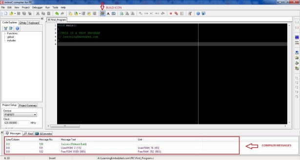
  • After completing your program, save it and click on the build icon as shown in the figure
  • If your program has no error then compiler will display a success message in the compiler messages area as shown in the figure above else the error messages will be displayed.Fix those errors(if any)
  • Hex file successfully created.Image may be NSFW.
    Clik here to view.
    PIC  First Project schematich

Steps to write your program to PIC microcontroller


Connect your PIC microcontroller to the PIC programmer.


  • Connect your PIC programmer to your computer.If you are connecting through your USB, you must first install this driver: PL2303
  • Download and Open Pickit 2 programmer software[Download Link].
  • If the device name is mentioned as shown in the figure below then it is successfully connected  .If not then check your connection and the programmer again.
  • Go to “File” in the menu and click on “Import Hex” and then go to the location where you have saved your MikroC project and select the .hex file  associated with your MikroC project.
  • After importing the .hex file change the VDD  PICkit 2 value to “5.0”  and click on “Write” as shown in the figure.


For more detail: PIC – First Project

The post PIC – First Project appeared first on PIC Microcontroller.

The Saltwater etch process using PIC16F54 microcontroller

The Saltwater etch process

This is a one-off process to produce one printed circuit board by removing unwanted copper by electrolysis in a saltwater solution.

I shall illustrate the process by etching and building a board for 18-pin PIC (for the PC16F54, but any 18 pin PIC will fit in it) in the figure. It has to plug into my breadboard and accept the programming signals from my PIC programmer (just go to http://geocities.com/it2n/circuits.html and look at it).

Image may be NSFW.
Clik here to view.
Saltwater etch process schematics

To avoid battling with signal conflicts, the two programming pins shall not be brought to the breadboard. To play around with the clock frequency, the crystal shall be made pluggable. The Master clear signal will not be brought out.

These decisions mean a board with two .1″ pitch connectors, one with 13 connections and the other with five connections, one pin spaced apart from the rest.

This is a tutorial intended for the absolute beginner, and almost every step shall be illustrated. I’ve even included a video of the etching process.

Step 1

Decide how large the board has to be

From the diagram, the side that plugs into the breadboard has 13 connections, and the holes in the bb are spaced 0.1 inch apart. So we need at least 1.3 inches to accommodate 13 pins.Say one and a half inches, a nice figure. Take a piece of copper clad board larger than 1.5 inches a side. Draw a line at one and a half inches.

Step 2

Score a line on the copper

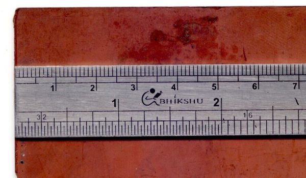
Hold your ruler or straightedge firmly down on the board. Hold a knife lightly and draw across the line many times.After some time, there will be a gouge on the copper, dividing it into two.

If you bear down with the knife, chances are that it might wander and cut the board deeply where you do not want it cut – and you will be looking ruefully down on your ruined PCB stock. Be patient. Being patient has its own virtues, as life will invariably teach you.

Step 3

Make that line a deeper groove

Now, you can take the ruler away and with a little more pressure on the knife, go over the line a few more times. It will be guided by the cut, and you need a groove on that side.
Then at each edge, mark the plain surface of the board and draw a line there, too, exactly on the other side.

Step 4

Score the other side

Image may be NSFW.
Clik here to view.
The Saltwater etch process

Now you need a groove on the other side of the laminate, too.You will have a board with grooves on both the sides, and bending it with the fingers will be sufficient to cause it to break neatly at this line.

This is the copper side, with a deep groove.

Step 5

Groove on the plain side

This is the plain side of the laminate, with that deep groove.

Step 6

Break it apart

If you look at the edge, you will see that the two grooves on the top and bottom of the sheet has made it weak at the line and it will break easily.

Step 7

The cut piece of PCB laminate

So we have cut the laminate to about one and a half inches. It is actually a bit more than that, and that is for allowances in finishing.It will need to be sanded down to make those edges smooth and that will take away a bit of material.

Step 8

Decide how large it has to be

Now we have to decide how large the board has to be on the other dimension.We need the two connectors, the PIC, the crystal, and some capacitors and one resistor.

Arranging them all on the board, it seems that about 2″ will be sufficient.

Step 9

Clean the board

Remove rough edges of the board using a sandpaper (Or go out and rub it on a level rough cement surface).Clean the copper surface using an abrasive cleaning pad – the one I use is intended for use in the kitchen, and copper is toxic so do not let your wife or mum relocate it to the kitchen after you have used it – it would also be a good idea not to borrow the one in the kitchen for this purpose.

The post The Saltwater etch process using PIC16F54 microcontroller appeared first on PIC Microcontroller.


The One Chip Spinning RGB POV Display with conversion software using PIC18f4680 microcontroller

The ‘One Chip Spinning RGB POV Display’ with conversion software.

If you have been on the look out for a project that combines, RGB LED’s, a motor, a microcontroller and a ridiculous amount of hot melt glue, then you have certainly come to the right place.
Allow me to introduce the ‘One Chip’ Spinning RGB POV Display

This project allows you to create (with minimal components) a fantastic customizable display capable of displaying graphics, animations and text. You can scroll your graphics from top to bottom or use it as a scrolling message display, scrolling from right to left.

The project uses just one chip, eight RGB LED’s and a handful of other components to paint animations in ‘mid-air!’ Plus, together with the included graphic conversion software (download link in step 2) you can easily create your own animations because the software creates all the code for you.

So please, read on and enjoy!

Step 1

Get your required parts and tools.

Before we set out on this venture, you will need both the components and tools.

Parts List:
1x PIC 18f4680 microcontroller
1 x 40 pin IC socket (optional – to house the microcontroller)
8 x Common cathode RGB LED’s
24 x 100 ohm resistors (any wattage)
1 x 0.1 uF capacitor (optional)
2 x 100 uF capacitors
1 x 7805 (5 Volt Regulator)
2 x 10k ohm resistors
1 x hall effect sensor / hall effect switch
1 x 5 pin header (to plug in the pickit2 programmer)
1 x small rare earth magnet (to be used with the sensor)
1 x screw in type mains wiring terminator (See last photo – you get these from a hardware store)
1 x 12v motor
1 x motor (any motor that you can destroy for parts – I.E. the graphite brushes)
1 x 12v powersupply (for the motor)
1 x 7.5 volt power supply (for the POV display – can be upto about 18v)
1 x (5.5cm x 5.5cm blank pcb – aka blank copper clad) – this will be used to transfer power to the display
Holt Melt Glue Sticks
Solder
Veroboard / experimenters board
Thin enamel wire (see pic)
Standard single core wire (Like they use in network cable)

Tools:
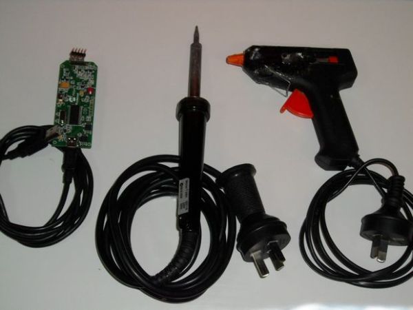
– Soldering Iron
– Screw Driver
– hot melt glue gun
– Stanley knife
– side cutters
– pliers
– pickit2 programmer
– desoldering tool (solder sucker or solder braid – just in case!)
– computer running windows
– swordfish basic compiler (this is a free download – it compiles the code for the microcontroller)
– POV Image Converter (Software that I have made, download link is included in the instructable)

Now that you have all of that, let’s get into the construction.

Step 2

Downloads

First and foremost, you will want to download the schematic so that you are not building this blindly, and perhaps you may want to experiment with the conversion software also. All these downloads are provided here:

Please read the readme.txt file for instructions on how to install the software.

Click this link to download the schematic:
http://www.bradsprojects.com/forum/download/file.php?id=297

Click this link to download the scroll down conversion software:
http://www.bradsprojects.com/forum/download/file.php?id=294

Click this link to download the scroll left conversion software:
http://www.bradsprojects.com/forum/download/file.php?id=290

Click this link to download swordfish basic (free version):
http://www.sfcompiler.co.uk/downloads/SwordfishSE.exe

Step 3

Let construction commence!

Now the beauty about this project is that you don’t have to make it exactly how I have made it.

my original intention was just for me to see how small a board I could fit this project onto. But as you will see, there is plenty of space to work with when we attach the main arm that connects the display to the motor. So by all means, have a look at my design – but there are certainly other ways (simpler ways) of achieving the desired outcome.

I have cut my board so that I have 26 holes by 10 holes.

Step 4

Solder in the LED’s and cut some tracks

Image may be NSFW.
Clik here to view.
Solder in the LED's and cut some tracks

I have used surface mount LED’s just to see how they would go (I have previously used through hole LED’s in a past project)

Solder the Red, Green and Blue connections to the board.

The three connections on the top are the cathodes. (this may differ for your LED’s – give them a quick check with your multimeter to verify)

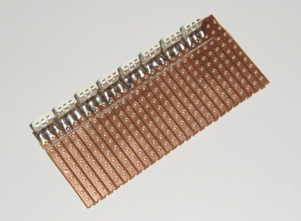
You will also notice I have cut a line through the tracks connected to the LED’s. This is so we can solder in some series resistors to limit each LED’s current.

IMPORTANT NOTE: You need to make sure that the bottom LED is connected as your least significant LED. I.E. this led will connect to PORTA pin 0, PORTB pin 0 and PORT D pin 0. You then work your way up from there. Follow the schematic and you will be fine = )

Step 5

Solder in your resistors.

I have also used surface mount resistors to keep my project small, you may very well want to use through hole to make things a little easier.

The resistors solder in over the tracks that you have just cut.

Step 6

Cut some more tracks and solder in a ground wire.

Now that the resistors are in place, you will want to cut another line of tracks on the other side of these resistors, getting them ready to solder to the microcontroller. – see the first photo

Once done, get a length of uninsulated wire and solder it along the length of the LED cathodes. then solder it to the veroboard (this will be our ground connection) – see second photo

For more detail: The One Chip Spinning RGB POV Display with conversion software using PIC18f4680 microcontroller

The post The One Chip Spinning RGB POV Display with conversion software using PIC18f4680 microcontroller appeared first on PIC Microcontroller.

A DDS Module based on the AD9835 using PIC16F84

Table of contents

Image may be NSFW.
Clik here to view.
DDS Module

Purpose

While working on a project I came across the DDS chips from Analog Devices. Especially the AD9835was very atractive to me because of its super simple handling and small size. Normaly you would use such a chip as a VFO or for other, similar functions but I decided to use it as a “Soundcard” for a project to do various digital RF modes with a PIC microcontroler. Some would say “I can do this with just the PIC and dont need a DDS chip”. That’s true but you would waste a lot of program memory for things like sine tables etc. With this solution you will have more memory available for your programs and you will get better signals than you could produce with just the PIC.

The AD9835 comes in a very smal TSSOP housing. So to start developing I needed a more bigger, better to handle form of the AD9835. I packed it with a 50 MHz osciliator module and some parts needed for propper operation on a small PCB with two connectors with standard pin sizes. This simplifies the development enormous. You now can use your standard breadboard to design systems with the AD9835.

After the hardware description you will find a code sample of a SSTV Testgenerator based on this module and a simple PIC 16F84. This shows that even uncommon digital modes can be done with a PIC. This Testgenerator produces a color bar screen using Martin-1 SSTV protocol and also sends the correct VIS code for Martin-1.

DISCLAIMER:
THIS CONTENT IS PROVIDED TO INTERESTED PEOPLE "AS IS" FOR NON COMERCIAL
PURPOSE ONLY. UNDER  NO CIRCUMSTANCES I AM RESPONSIBLE  FOR ANY DAMAGES 
TO  YOUR RADIO, PC OR OTHER  EQUIPMENT. THIS  DEVICE  WAS TESTED  UNDER 
DIFFERENT  CONDITIONS   AND  UNTIL  NOW  IT  WORKS   WITHOUT  PROBLEMS.

Schematics

This is the schematic of the AD9835 Module. It follows in some parts the schematic in the AD9835 reference manual. Other parts could be better. For example the power handling (Analog and Digital VDD and VSS) is not that optimal as it could be (just L1 to prevent some disturbances).

Image may be NSFW.
Clik here to view.
Schematic DDS Module

The PCB
The PCB is single sided and except the 50 MHz oscillator module and the coil which are of normal size all other components are SMD size 1206. Special care must be taken soldering the AD9835. It comes as a TSSOP and unless you don’t have a soldering iron with a very, very fine tip and a magnifying glass you wont get happy builing this project. Be warned! This chip is hard to solder.

The red marked lines on the PCB are simple jumper wires which must be soldered from the non copper side of the board. For more details see the pictures.


For more detail: A DDS Module based on the AD9835 using PIC16F84


The post A DDS Module based on the AD9835 using PIC16F84 appeared first on PIC Microcontroller.

Building your own Simple Laser Projector using the Microchip PIC12F683 Microcontroller

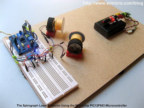
The 8 pins PIC12F683 microcontroller is one of the smallest members of the Microchip 8-bit microcontroller families but equipped with powerful peripherals such as ADC and PWM capabilities. This make this tiny microcontroller is suitable for controlling the DC motor speed. In order to demonstrate the PIC12F683 capabilities and to make this tutorial more attractive, I decided to use the PIC12F683 microcontroller to generate simple and yet fascinating laser light show from a cheap keychain laser pointer.

Image may be NSFW.
Clik here to view.
Building your own Simple Laser Projector

The basic of laser light shown in many entertainments club or park mostly use two method; the first one is to beam the laser shower on the spectators and the second one is to display the laser drawing pattern on the screen. On this tutorial we are going to build the laser projector that displays the spirograph pattern on the screen using the tiny Microchip PIC12F683 microcontroller.

The principle of making the spirograph laser projector is to use at least two DC motors with the attached mirror on it, these mirrors then will deflect the laser beam from one DC motor mirror to the second DC motor mirror and then finally to the screen. By controlling each of the DC motors spinning speed we could generate a fascinating laser spirograph pattern on the screen as shown on this following picture.

The best way to control the DC motor speed is to use the PWM (pulse wave modulation) signal to drive the DC Motor and because we want to change the DC motor speed manually, therefore we need to use the trimport or potentiometer to control each of the DC motors speed. Hmm, this sound like an appropriate job for the microcontroller but could we use this tiny 8 pins PIC12F683 microcontroller to handle this task?

From the datasheet you will notice that the Microchip PIC12F683 microcontroller only has one PWM output (CCP1) and four ADC input channel (AN0, AN1, AN2 and AN3). Because we need two PWM output, therefore instead of using the PIC12F683 microcontroller build in PWM peripheral, in this tutorial I will show you how to generate the PWM signal base on the PIC12F683 microcontroller TIMER0 peripheral. The following is the complete electronic schematic for the laser projector project.

Ok before we go further with the detail; let’s list down the supporting peripherals needed to complete this laser projector project:

  • Hot glue gun
  • Keychain laser pointer or any available laser pointer
  • 3xAA, 4.5 volt battery holder for powering the laser pointer, please use the same voltage rate used by your laser pointer.
  • Two DC motor taken from the discarded PS2 Dual shock joystick
  • Two toy’s car tire taken from tamiya racing car
  • CD/DVD for the mirror, use a kitchen scissor to cut the CD/DVD into the two circle shape mirror with approximately 38 mm in diameter
  • Some toys plastic bricks for holding the DC motor
  • Breadboard
  • Hardboard or acrylic is used for the base of our laser projector
  • Double Tape

The following are the electronic parts and the software development tools that I used to make this laser projector project:

  • Resistor: 330 (3), 1K (5) and 10K (1)
  • Trimport: 10K (2)
  • Capacitor: 100nF (2) and 10nF (1)
  • One 100uH Inductor
  • Two 1N4148 Diodes
  • Two Blue and one Red Light Emitting Diode (LED)
  • Two 2N2222A transistors
  • One Mini Push Button Switch
  • One Microchip PIC12F683 Microcontroller
  • Microchip MPLAB v8.46 IDE (Integrated Development Environment)
  • Microchip Macro Assembler MPASMWIN.exe v5.35, mplink.exe v4.35
  • HI-TECH C Compiler for PIC10/12/16 MCUs (Lite Mode) V9.70
  • Microchip PICKit3 Programmer (Firmware Suite Version: 01.25.20)

This project is aim as the continuing lessons to my previous posted blog Introduction to PIC Assembly Language Part-1 and Introduction to PIC Assembly Language Part-2, therefore I used the same PIC12F683 board presented in the part 2 which you could down load both of the electronic schematic and the PCB layout designed in Eagle CAD format. The other interesting feature of this laser projector project is; besides the PIC assembly code I also provide the C language version of this project for the C language lover and is compiled with the HI-TECH C Compiler (recently the HI-TECH Software has been acquired by Microchip). This C language version could be used for learning as well as the embedded system programming language comparison.

In this project I also use a new Microchip PICKit3 programmer but of course you could use the Microchip PICKit2 programmer to download the hex code to the PIC12F683 microcontroller flash.

Image may be NSFW.
Clik here to view.
Building your own Simple Laser Projector using the Microchip PIC12F683

The following is the Laser Projector code in PIC Assembly Language:

;******************************************************************************
;  File Name    : laserlight.asm
;  Version      : 1.0
;  Description  : Laser Light Show Project
;  Author       : RWB
;  Target       : Microchip PIC12F683 Microcontroller
;  Compiler     : Microchip Assembler (MPASMWIN.exe v5.35, mplink.exe v4.35)
;  IDE          : Microchip MPLAB IDE v8.46
;  Programmer   : PICKit3 (Firmware Suite Version: 01.25.20)
;  Last Updated : 01 April 2010
; *****************************************************************************
#include <p12F683.inc>
__config (_INTRC_OSC_NOCLKOUT & _WDT_OFF & _PWRTE_OFF & _MCLRE_OFF & _CP_OFF & _IESO_OFF & _FCMEN_OFF)
#define MAX_TMR0 0xFB
#define MAX_COUNT .200
#define MAX_DEBOUNCE 0x0A
#define MAX_TBLINDEX 0x0A
; Define variables used
     cblock 0x20
Delay:2                      ; Define two registers for the Delay and Delay + 1
mode                         ; Operation Mode
pwm_count                    ; Hold the Main PWM Counter
pwm_m1                       ; Hold the PWM width for Motor 1
pwm_m2                       ; Hold the PWM width for Motor 2
keycount                     ; Debounce Count
tableindex                   ; Table Index for Auto PWM
     endc
; Define variable use for storing STATUS and WREG register
     cblock 0x70             ; Use unbanked RAM, available both in Bank0 and Bank1
saved_w
saved_status
     endc
; Start the Light show Assembler Code here
     org 0x00                ; We always start at flash address 0
     goto Main               ; Jump to Main
     org 0x04                ; 0x04: Start PIC Interrupt Address
PIC_ISR:                     ; Start the PIC Interrupt Service Routine
     movwf   saved_w         ; Save Working Register
     movf    STATUS,w        ; Save Status Register
     movwf   saved_status
; Check the TIMER0 Interrupt here
     btfss   INTCON,T0IF
     goto    ExitISR         ; If (T0IF != 1) then Exit ISR
     bcf     STATUS,RP0      ; Select Registers at Bank 0
     incf    pwm_count       ; pwm_count++
     movlw   MAX_COUNT
     subwf   pwm_count,w     ; if (pwm_count < MAX_COUNT) then CheckPWM
     btfss   STATUS,C        ; else clear GP1 and GP2
     goto    CheckPWM
     bcf     GPIO,GP1        ; GPIO1=0
     bcf     GPIO,GP2        ; GPIO2=0
     goto    ExitPWM
CheckPWM:
     movf    pwm_m1,w
     subwf   pwm_count,w
     btfsc   STATUS,Z        ; if (pwm_count == pwm_m1) then Set GP1
     bsf     GPIO,GP1        ; Set GP1 Bit
CheckM2:
     movf    pwm_m2,w
     subwf   pwm_count,w
     btfsc   STATUS,Z        ; if (pwm_count == pwm_m2) then Set GP2
     bsf     GPIO,GP2        ; Set GP2 bit
ExitPWM:
     bcf     INTCON,T0IF     ; clear the TIMER0 interrupt flag
     movlw   MAX_TMR0
     movwf   TMR0            ; TMR0 = MAX_TMR0
ExitISR:
     movf    saved_status,w
     movwf   STATUS          ; Restore STATUS Register
     swapf   saved_w,f
     swapf   saved_w,w       ; Restore W Register
     retfie                  ; Return from Interrupt
Main:
     bsf     STATUS,RP0      ; Select Registers at Bank 1
     movlw   0x70
     movwf   OSCCON          ; Set the internal clock speed to 8 MHz
     movlw   0x39            ; GP1 and GP2 Output, GP0,GP3,GP4 and GP5 as Input
     movwf   TRISIO          ; TRISIO = 0x39        

     bcf     STATUS,RP0      ; Select Registers at Bank 0
     movlw   0x07
     movwf   CMCON0          ; Turn off Comparator (GP0, GP1, GP2)
     clrf    GPIO

; Now we Set the ADC Peripheral
     bsf     STATUS,RP0      ; Select Registers at Bank 1
     movlw   0x79            ; Set AN0 (GP0) and AN3 (GP4) as Analog Input
     movwf   ANSEL           ; Using the Internal Clock (FRC)  

; Now we set the TIMER0 Peripheral
; TIMER0 Period = 1/FSOC x 4 x Prescale x TMR0
     movlw   0x00            ; Use TIMER0 Prescaler 1:2, Internal Clock
     movwf   OPTION_REG      ; OPTION_REG = 0x00
     bcf     STATUS,RP0      ; Select Registers at Bank 0
     movlw   MAX_TMR0
     movwf   TMR0            ; TMR0=MAX_TMR0      

; Initial the variables used
     clrf    mode            ; Default mode = 0, Light Show Off
     clrf    pwm_count       ; pwm_count = 0
     clrf    pwm_m1          ; pwm_m1 = 0
     clrf    pwm_m2          ; pwm_m2 = 0
     clrf    keycount        ; keycount = 0
     clrf    tableindex      ; tableindex = 0
; Activate the Interrupt
     bsf     INTCON,GIE      ; Enable Global Interrupt
MainLoop:
     btfsc   GPIO,GP5        ; Now we check the Button
     goto    CheckMode       ; if (GP5 != 0) goto CheckMode
     movlw   0x01
     addwf   keycount        ; keycount=keycount + 1
     movf    keycount,w
     sublw   MAX_DEBOUNCE
     btfss   STATUS,C        ; if (keycount > MAX_DEBOUNCE) goto KeyPressed
     goto    KeyPressed
     goto    CheckMode       ; else CheckMode
KeyPressed:
     clrf    keycount        ; keycount=0
     incf    mode            ; mode++
     movlw   0x03
     subwf   mode,w          ; W = mode - 0x03
     btfsc   STATUS,C        ; if (mode >= 0x03)
     clrf    mode            ; mode=0;
     movlw   0x01            ; else check the mode
     subwf   mode,w
     btfss   STATUS,C        ; if (mode >= 0x01) goto TurnOn
     goto    TurnOff         ; else goto TurnOff
     goto    TurnOn
TurnOff:
     bcf     INTCON,T0IE     ; Disable TIMER0 Interrupt
     clrf    pwm_count       ; pwm_count = 0
     clrf    pwm_m1          ; pwm_m1 = 0
     clrf    pwm_m2          ; pwm_m2 = 0
     bcf     GPIO,GP1
     bcf     GPIO,GP2
     movlw   .250
     call    DelayMs         ; DelayMs(250)
     movlw   .250
     call    DelayMs         ; DelayMs(250)
     goto    CheckMode
TurnOn:
     bsf     INTCON,T0IE     ; Enable TIMER0 Interrupt                    

CheckMode:
     movlw   0x01
     subwf   mode,w
     btfss   STATUS,Z        ; if (mode == 1) goto ShowMode1
     goto    CheckMode2
     goto    ShowMode1
CheckMode2:
     movlw   0x02
     subwf   mode,w
     btfss   STATUS,Z        ; if (mode == 2) goto ShowMode2
     goto    KeepLoop
     goto    ShowMode2
ShowMode1:                   ; Used ADC for PWM
     movlw   B'00000001'     ; Left Justify and turn on the ADC peripheral, channel 0 (AN0)
     movwf   ADCON0          ; Vreff=Vdd
     bsf     ADCON0,GO       ; Start the ADC Conversion on channel 0 (AN0)
     btfss   ADCON0,GO       ; while(GO == 1)
     goto    $-1             ; Keep Loop
     call    Delay1ms
     movlw   B'00000001'     ; Left Justify and turn on the ADC peripheral, channel 0 (AN0)
     movwf   ADCON0          ; Vreff=Vdd
     bsf     ADCON0,GO       ; Start the ADC Conversion on channel 0 (AN0)
     btfss   ADCON0,GO       ; while(GO == 1)
     goto    $-1             ; Keep Loop
     movf    ADRESH,w        ; Conversion Done, Read ADRESH
     movwf   pwm_m1          ; pwm_m1 = ADRESH
     call    Delay1ms

     movlw   B'00001101'     ; Left Justify and turn on the ADC peripheral, channel 3 (AN3)
     movwf   ADCON0          ; Vreff=Vdd
     bsf     ADCON0,GO       ; Start the ADC Conversion on channel 3 (AN3)
     btfss   ADCON0,GO       ; while(GO == 1)
     goto    $-1             ; Keep Test
     call    Delay1ms
     movlw   B'00001101'     ; Left Justify and turn on the ADC peripheral, channel 3 (AN3)
     movwf   ADCON0          ; Vreff=Vdd
     bsf     ADCON0,GO       ; Start the ADC Conversion on channel 3 (AN3)
     btfss   ADCON0,GO       ; while(GO == 1)
     goto    $-1             ; Keep Test
     movf    ADRESH,w        ; Conversion Done, Read ADRESH
     movwf   pwm_m2          ; pwm_m2 = ADRESH
     call    Delay1ms
     goto    KeepLoop
ShowMode2:                   ; Used Predefined Value for PWM
     movf    tableindex,w
     call    tablepwm1       ; Call tablepwm1
     movwf   pwm_m1          ; Assigned it to pwm_m1
     movlw   .30
     call    DelayMs         ; DelayMs(30)

     movf    tableindex,w
     call    tablepwm2       ; Call tablepwm2
     movwf   pwm_m2          ; Assigned it to pwm_m2
     movlw   .30
     call    DelayMs         ; DelayMs(30)
     incf    tableindex      ; tableindex++
     movlw   MAX_TBLINDEX
     subwf   tableindex,w
     btfss   STATUS,C        ; if (tableindex >= 0x0A) then tableindex = 0
     goto    KeepLoop
     clrf    tableindex      ; tableindex = 0
KeepLoop:
     goto    MainLoop        ; Goto MainLoop
; Predefined value table for Automatic PWM
tablepwm1:
     addwf   PCL,f
     retlw   0x10
     retlw   0x5A
     retlw   0x9A
     retlw   0x20
     retlw   0x40
     retlw   0x8A
     retlw   0x82
     retlw   0x30
     retlw   0x58
     retlw   0xAA
tablepwm2:
     addwf   PCL,f
     retlw   0x70
     retlw   0x8A
     retlw   0x2A
     retlw   0x30
     retlw   0x1C
     retlw   0x2A
     retlw   0x4B
     retlw   0xA0
     retlw   0x18
     retlw   0x2A
;----------------- DelayMs: Millisecond Delay Subroutine ----------------------
; Paramater: WREG = delay amount in milisecond, max: 255 millisecond
DelayMs:
     movwf   Delay + 1
DelayLoop:
     call    Delay1ms
     decfsz  Delay + 1,f     ; Decrease Delay + 1, If zero skip the next instruction
     goto    DelayLoop       ; Not zero goto DelayLoop
     return                  ; return to the caller
;----------------- Delay1ms: 1 ms Delay Subroutine ---------------------------
Delay1ms:                    ; Total Delay: 1998 x 0.5us ~ 1 ms
     movlw   0x99
     movwf   Delay
DelayLoop1:
     decfsz  Delay,f         ; Decrease Delay, If zero skip the next instruction
     goto    DelayLoop1
DelayLoop2:
     decfsz  Delay,f         ; Decrease Delay, If zero skip the next instruction
     goto    DelayLoop2      ; Not zero goto DelayLoop2
DelayLoop3:
     decfsz  Delay,f         ; Decrease Delay, If zero skip the next instruction
     goto    DelayLoop3      ; Not zero goto DelayLoop2
     return                  ; Return to the caller
     end
; EOF: laserlight.asm

The following is the Laser Projector Project code in C Language version:

// ***************************************************************************
//  File Name    : laserlight.c
//  Version      : 1.0
//  Description  : Laser Light Show Project
//  Author       : RWB
//  Target       : Microchip PIC12F683 Microcontroller
//  Compiler     : HI-TECH C PIC10/12/16 MCUs (Lite Mode) V9.70
//  IDE          : Microchip MPLAB IDE v8.46
//  Programmer   : PICKit3 (Firmware Suite Version: 01.25.20)
//  Last Updated : 03 April 2010
// ***************************************************************************
#include <pic.h>
/*   PIC Configuration Bit:
**   INTIO     - Using Internal RC No Clock
**   WDTDIS    - Wacthdog Timer Disable
**   PWRTEN    - Power Up Timer Enable
**   MCLRDIS   - Master Clear Disable
**   UNPROTECT - Code Un-Protect
**   UNPROTECT - Data EEPROM Read Un-Protect
**   BORDIS    - Borwn Out Detect Disable
**   IESODIS   - Internal External Switch Over Mode Disable
**   FCMDIS    - Monitor Clock Fail Safe Disable
*/
__CONFIG(INTIO & WDTDIS & PWRTEN & MCLRDIS & UNPROTECT \
  & UNPROTECT & BORDIS & IESODIS & FCMDIS);
// Using Internal Clock of 8 MHz
#define FOSC 8000000L
#define MAX_COUNT 200
#define MAX_TMR0 0xFB
#define MAX_DEBOUNCE 0x0A
#define MAX_TBLINDEX 0x0A
unsigned char pwm_count=0;
unsigned char pwm_m1=0;
unsigned char pwm_m2=0;
unsigned char tablepwm1[10]={0x10,0x5A,0x9A,0x20,0x40,0x8A,0x82,0x30,0x58,0xAA};
unsigned char tablepwm2[10]={0x70,0x8A,0x2A,0x30,0x1C,0x2A,0x4B,0xA0,0x18,0x2A};
unsigned char tableindex=0;
/* The Delay Function */
#define	delay_us(x) { unsigned char us; \
			        us = (x)/(12000000/FOSC)|1; \
			        while(--us != 0) continue; }
void delay_ms(unsigned int ms)
{
  unsigned char i;
  do {
    i = 4;
    do {
      delay_us(164);
    } while(--i);
  } while(--ms);
}
static void interrupt isr(void)
{
  if(T0IF) {	       // TIMER0 Interrupt Flag
    pwm_count++;       // PWM Count Increment
    if (pwm_count >= MAX_COUNT) {
      pwm_count=0;
      GPIO1=0;         // Turn off GP1
      GPIO2=0;         // Turn off GP2
    }
    if (pwm_count == pwm_m1) {
      GPIO1=1;         // Turn On GP1
    }    

    if (pwm_count == pwm_m2) {
      GPIO2=1;         // Turn On GP2
    }      

    TMR0 = MAX_TMR0;   // Initial Value for TIMER0 Interrupt
    T0IF = 0;	       // Clear TIMER0 interrupt flag
  }
}
void main(void)
{
  unsigned char mode,keycount;
  OSCCON=0x70;         // Select 8 MHz internal clock
  /* Initial Port Used */
  TRISIO = 0x39;       // GP1 and GP2 Output, GP0,GP3,GP4 and GP5 as Input
  CMCON0 = 0x07;       // Turn off Comparator (GP0, GP1, GP2)
  GPIO = 0x00;         // Turn Off all IO
  /* Init ADC Peripheral */
  ANSEL = 0x79;        // Set AN0 (GP0) and AN3 (GP4) as Analog Input, Internal Clock
  /* Init TIMER0: TIMER0 Period = 1/FSOC x 4 x Prescale x TMR0*/
  OPTION = 0b00000000; // 1:2 Prescale
  TMR0=MAX_TMR0 ;
  /* Init Variable Used */
  pwm_count=0;
  pwm_m1=0;
  pwm_m2=0;
  mode=0;
  keycount=0;
  tableindex=0;
  GIE =1;		       // Enable Global Interrupt

  for(;;) {
    // Display the LED
    if (GPIO5 == 0) {
      keycount++;
      if (keycount > MAX_DEBOUNCE) {
        keycount=0;
        mode = mode + 1;
        if (mode > 2) mode = 0;
        if (mode >= 0x01) {
          T0IE = 1;	       // Enable TIMER0 Interrupt on Overflow
        } else {
          T0IE = 0;	       // Disable TIMER0 Intterupt on Overflow
          pwm_count=0;
          pwm_m1=0;
          pwm_m2=0;
          GPIO1=0;             // Turn off GP1
          GPIO2=0;             // Turn off GP2
          delay_ms(500);
        }
      }
    }
    if (mode == 1) {
      /* Read the ADC here */
      ADCON0=0b00000001;       // select left justify result. ADC port channel AN0
      GODONE=1;	               // initiate conversion on the channel 0
      while(GODONE) continue;  // Wait for ldr_left conversion done
      pwm_m1=ADRESH;           // Read 8 bits MSB, Ignore 2 bits LSB in ADRESL
      delay_ms(1);
      /* Read the ADC here */
      ADCON0=0b00001101;       // select left justify result. ADC port channel AN3
      GODONE=1;	         // initiate conversion on the channel 4
      while(GODONE) continue;  // Wait for ldr_left conversion done
      pwm_m2=ADRESH;           // Read 8 bits MSB, Ignore 2 bits LSB in ADRESL     

      delay_ms(1);
    }
    if (mode == 2) {
      pwm_m1=tablepwm1[tableindex];
      delay_ms(10);
      pwm_m2=tablepwm2[tableindex];
      delay_ms(10);
      tableindex++;
      if (tableindex >= MAX_TBLINDEX)
        tableindex = 0;
    }
  }
}
/* EOF: laserlight.c */

Generating the PWM (Pulse Width Modulation)


For more detail: Building your own Simple Laser Projector using the Microchip PIC12F683 Microcontroller

The post Building your own Simple Laser Projector using the Microchip PIC12F683 Microcontroller appeared first on PIC Microcontroller.

DMM Piggyback (add RS-232) using PIC16F688 microcontroller

DMM Piggyback (add RS-232)

There are mods that give a multimeter serial connectivity by soldering some pins but, it only works if it already has RS-232 ability. So I decided rather than building a PIC multimeter from scratch, I would Piggyback off a $4 DMM.

I used:
one PIC16F688
one LM358
a button and a 100k potentiometer
3 resistors (1k 10k 20k)
A PCB, piece of thin plastic, and hardware
Despite the low part count assembly and programing can be a little troublesome.

Step 1

Image may be NSFW.
Clik here to view.
DMM Piggyback

The Theory

This mod uses all the Voltage, Current, Resistance, and hFE circuitry of the original DMM.
Since the meter is relatively cheap it has bed of nails test points (found on electronics with a “blob” IC)
These points are a circuit benders dream.
I just pulled the input to the original chip (I will call the golden pin) amped it, ran it through the PIC, and sent it through serial. I also used a potentiometer to encode the selector dial.
The golden pin is the middle pin of the left side (circled in red)
DO NOT SOLDER TO THE LARGE PAD EVEN THOUGH ITS CONNECTED TO THE PIN THOUGH A CAPACITOR

Step 2

The Circuit

Image may be NSFW.
Clik here to view.
schematics of DMM Piggyback

Power is supplied by the power pin to the original IC (on bottom 4th from the right) and the common lead (banana jack). It gives 6V and uses the built in power switch.
The op amp is set up as 11x voltage amp from the golden pin. I used an amp because the pin only gives 200mV on full DC voltage signal. The amp feeds AN0 of the pic. The pot goes to AN7 no amp needed and hooks to the same power as the PIC and OP AMP

USE ONLY LM358 OR EQUIVALENT. LM741 DOES NOT WORK!

Step 3

The Dial Encoder

This was probably the hardest part to figure out, and my solution is far from perfect.I used a PCB mount micro pot (1.69 at radio shack) and curled the leads around to mount it. (this also makes it continues rotation)

To mount it cut a thin plastic sheet (like the DMM’s container) to fit to the screw holes.
then cut a hole for the pot (make it a tight fit) I also cut a hole for the diode, lead board solder, and power leads
take out the screws slip the pot in the plastic and screw it down.(I pre drilled screw holes)

I used  a screw and cut the head flat(see last pic keep green part) to couple the dial and pot together.
The screw fits nice in the hollow center of the dial.
The flat head goes into the flat-head screw hole on the pot.
I suggest using red lock tight because if the screw losens the encoder stops working.

The post DMM Piggyback (add RS-232) using PIC16F688 microcontroller appeared first on PIC Microcontroller.

Aurora mini 18 using PIC24FV16KA302 microcontroller

Aurora mini 18

My obsession of this year is full-color LED. I have made Aurora 9×18 as a result. As much as I love the scale of Aurora 9×18, I also wanted to have something smaller, perhaps something that can go on a costume?

Image may be NSFW.
Clik here to view.
Aurora mini 18 RGB

Here’s Aurora mini 18. It has 18 full-color/RGB LEDs on a smallest possible circle. With a single PIC microcontroller, changing 18 RGB LEDs smoothly is reaching the technical limit. With the new PIC with wider supply voltage, the circuit is simplified compared to Aurora 9 bar, and use of two AA or AAA batteries (3V operation) or one Lithium battery is now possible.

Step 1

Concept & Circuit


Image may be NSFW.
Clik here to view.
schematics of  Aurora mini 18

Like Aurora 9 bar, Aurora mini 18 borrows its circuit from Aurora 9×18. Operating principle is exactly the same. Just extended the hardware and software to control more LEDs.
One of the new 24F line of PIC microcontrollers is PIC24FV16KA302. Unlike the similar PIC24F series controllers which are 3.3V limited, this controller can operate fully up to 5V. This eliminated the need for the 3.3V voltage regulator, and simplified the LED driving circuits. The resulted circuit with fewer parts count made this Aurora to be very compact.

Step 2

PCB & Parts

Aurora mini 18 uses surface-mount technology (SMT). If you’ve never built anything with SMT, this might be a good opportunity to try out. You will most likely realize that there’s nothing to fear about SMT. (If you are not familiar with soldering, you might get your feet wet with something simpler than this though.)
The high-quality, custom made PCBs as well as the full kits are available at a reasonable price. Please view the details at “For Sale” section of the forums.
Parts
Here is the list of parts. All except LEDs are available at Digi-Key (digikey.com).
  • 1x 10k Ohm (0603)
  • 3x 220 Ohm (0603)
  • 3x 2.2k Ohm (0603)
  • 18x 150 Ohm (0603)
  • 2x 0.1uF (0603)
  • 2x 10uF (1206)
  • 3x Q1x: MMBT2907A
  • 1x PIC24FV16KA302 (SS)
  • 18x Tricolor LED (common-cathode) (SparkFun COM-09264 should be identical) http://www.sparkfun.com/products/9264
  • 1x Tactile Switch
  • 1x 3 – 5V power supply: regulated AC adaptor, 4 NiMH, 2 AA/AAA batteries & case, single cell Lithium battery, or USB cable
  • 1x 2 pin Molex header (right-angle recommended) (optional)
  • 1x 2 pin Molex connector with corresponding terminals (optional)
There are many places to purchase LEDs. I source LEDs directly from China via AliExpress. Takes a few weeks for delivery, but the prices are great. (If you are purchasing a lot of LEDs.)

You can substitute transistors if you have something compatible.

The post Aurora mini 18 using PIC24FV16KA302 microcontroller appeared first on PIC Microcontroller.

How to use PIC16F84A pin as input (Code+Proteus simulation)

This post provides an example code to use PIC16F84A pins as inputs. After going through this example, you will understand how to make PIC16F84A pins as inputs and how to read their value in the code. This code is written in C language using MPLAB with HI-TECH C compiler.You can download this code from the ‘Downloads‘ section at the bottom of this page.

Image may be NSFW.
Clik here to view.
Use PIC16F84A pin as input

It is assumed that you know how to blink an LED with PIC16F84A microcontroller. If you don’t then please read this page first, before proceeding with this article.

Following figure shows the circuit used to demonstrate how to get input in PIC16F84A micro-controller.

In this figure, PIC16F84A is running on external crystal of 20MHz[1]. RA0 pin is being used as the input pin. When the push button is in the pushed state then, RA0 pin is high, otherwise RA0 pin is low. Whenever RA0 pin is high, then RB0 pin (Attached with the LED) is also made high just to indicate correct reading of RA0 pin status in the micro-controller.

Code

The code for reading the status of RA0 pin is shown below.

Image may be NSFW.
Clik here to view.
Use PIC16F84A pin as input schematic

Downloads

Input pin code using PIC16F84A was compiled in MPLAB v8.85 with HI-TECH C v9.83 compiler and simulation was made in Proteus v7.10. To download code and Proteus simulation click here.


For more detail: How to use PIC16F84A pin as input (Code+Proteus simulation)

The post How to use PIC16F84A pin as input (Code+Proteus simulation) appeared first on PIC Microcontroller.

picLink RS232 low cost development controller with ADC using PIC16F628A

PicLink RS232 low cost development controller with ADC

PICLink RS232 Embedded Controller

The PICLink RS232 controller module affords any microcontroller enthusiast an
easy to construct mini-microcontroller module. This embedded microcontroller is
ICSP (in circuit serial) programmable and provides separate PORTA, PORTB,
RS232 I/O ports, 4 Channel Analog to Digital converter as well as an integrated ICSP port to implement in circuit  programming and debugging. On board host RS232 USART may be used to interface with a PC (USB to RS232) or any other serial communications device like our 2.4 GHz Wi-Fi or 915MHz wireless modules. In this instructable you will need to manufacture a double sided circuit board (circuit board dimensions are given below), assemble the board with the necessary components (see components list) and then program the controller with LES firmware version 1.1.  For this you will need an ICSP programmer such as the USBPIC Programmer   or the PICKit 2 which is what I currently use as an engineer and firmware developer.  I would recommend for those whom are serious about embedded device engineering spending the $30 dollars (USD) for the PICKit. The PICKit2  LogicTool will serve to be a great development tool when developing embedded control devices.

Image may be NSFW.
Clik here to view.
PIC LINK

LES 1.1 Firmware

LES-1.0 (version 1.0) is a miniaturized embedded framework written in
C currently for PIC micro-controllers which supports basic input/output, memory
and RS232 asynchronous communications. Because of its small foot print the
entire system can fit into 1K (1024 Bytes) of program memory. In addition LES
greatly simplifies bit level control of IO ports through macros like BIT_SET,
BIT_CLEAR, BIT_IS_SET and BIT_COMP. Port register control
is achieved through PORTx macros which reduce bit level TRISx calls this saving
critical program memory space.

LES 1.1 Firmware was developed using Eclipse SDCC and GPUTILS. The PICLink (LES) build environment is simple to set up and requires no proprietary licensed software. SDCC and GPUTILS are opensource development tools published under the GNU Public License agreement and are free for download and use.  As soon as I get a chance I will update the LES article with download and SDCC install instructions.

URF 1000 Sonar  

The PICLink RS232 embedded controller was developed to calculate distance and transmit telemetric data to host terminal when interfaced with TuxMicro’s URF 1000 Series Ultrasonic Sonar Range Finder DSM module.

Features

· Supply Voltage – 5.0 to 5.5 VDC H1-2
· Supply Current – 10 mA typ
· ICSP (In-Circuit Serial Programmable)
Supports Microchip device debugging via H1
· 20 MHz Crystal controlled SBC
· 11 bi-directional I/O Pins
· 4 channel ADC (PORTA)
· Dedicated RS232 USART Port 120 kbit/s
· RS232 speeds 1200 to 155200 bit/s
· 128 Bytes EEPROM
· 224 Bytes SRAM
· 2 K Bytes program memory (1k when running LES)
· LES firmware version 1.1

Module Dimensions

52.5 mm L x 41 mm W x 1.6mm H (2.06in x 1.61 in x 0.63 in)

PicLink Mother Board fabrication – Bottom Layer

Circuit Board fabrication materials using DirectEtch

Toner Transfer pape r, environmentally friendly etchant (2oz hydrogen peroxide mixed with 1oz muriatic acid) a plastic well of water (sandwich container or 8″ brownie pan), paper towel, plastic gloves, sandwich container (found at Dollar Tree two for one dollar), fine steel wool and a small can of Acetone to remove the toner foil “resist” image from the board after etching. You will need either a laser printer or copier to transfer copies of the circuit templates to the toner transfer paper. Also it would be extra easy is you could gain access to a laminator such as a GBC Creative Laminator. The GBC Creative Laminator makes producing double sided circuit boards very easy since both sides of the circuit board is heated evenly during the toner transfer to circuit board.

1/2oz Copper, .032″ thick Double Sided Copper clad circuit board is recommended to make this product since it can be cut with a pair of heavy duty utility scissors.

Cut a piece of double sided board to 55mm x 45mm then clean both surfaces with Acetone and buff with fine steel wool until a mirror finish is obtained. For best results after buffing clean sides with Denatured alcohol or Marine stove fuel.

PicLink Mother Board fabrication – Top Layer

Toner Transfer Direct-etch 

Reproduce image art of circuit board onto a single sheet of 8.5 x 11″ toner transfer paper shiny side to to image. Be sure to handle the materials with plastic gloves on since the oils in one skin can distort the image quality.

How to make Direct Etch Transfer paper 

Toner Transfer paper is business card stock with a layer of Dextrin (cooked corn starch). Dextrin can be made from ARGO Corn Starch by sprinkling a thin layer of corn starch on a cookie sheet an baking in an oven at 350° F for 120 minutes. During the baking cycle it is necessary to stir the starch at 30 minute intervals to help insure even drying. After baking the cornstarch the dried powder (Dextrin) can be mixed with water to make paste (approximately 1.5 tablespoons of powder to one cup of water). Kiwi Water repellent (silicone spray) is then applied to a sheet of the paper stock dried and then coated with a thin layer of Dextrin paste. Once the paste dries you have homemade Toner Transfer Paper ready to make circuit boards.

After circuit board is cut, polished, washed with solvent it is ready for transfer of image art.
Image may be NSFW.
Clik here to view.
Schematic PIC LINK

Once art is copied onto a sheet of Toner Transfer paper the art is then cut out in squares so that the target symbols on both top and bottom layers will match up when facing each other. Remember your image must be on the shiny side of the transfer paper so that when both top and bottom images face each other the circuit trace donuts will line up. This is necessary to check since the copper clad board will actually be placed between these two sheets and taped with Scotch tape on one end in order to help prevent slippage.  Keeping this in mind lay out the squares of art as to make a laminator pouch from them by taping one end together while insuring the two images and target symbols mate evenly.

The post picLink RS232 low cost development controller with ADC using PIC16F628A appeared first on PIC Microcontroller.


embedded microchip

Microchip Technology Inc. is a Leading Provider of Microcontroller and . (Nasdaq: MCHP) Manufactures and markets a variety of VLSI CMOS semiconductor components to support the embedded control market.www.microchip.com – 143k – CachedMicrochImage may be NSFW.
Clik here to view.
embedded microchip
Microchip Technology Inc. is a Leading Provider of Microcontroller and . (Nasdaq: MCHP) Manufactures and markets a variety of VLSI CMOS semiconductor components to support the embedded control market.www.microchip.com – 143k – CachedMicrochip
Contrary view: Microchip is pretty smart to make a move on Atmel . Embedded.com > Columns. Microchip and Atmel . of programming embedded processors: Part 1 .
NEW EMBEDDED ETHERNET Controller by Microchip with MAC and PHY is .
NEW EMBEDDED ETHERNET Controller by Microchip with MAC and PHY is World’s Smallest . Microchip’s ENC28J60 Embedded Ethernet Controller enables designers to create .
NEW EMBEDDED ETHERNET on Microchip PIC18 Microcontrollers
New Embedded Ethernet on Microchip PIC18 Microcontrollers. By Bill Giovino . Embedded Ethernet projects an be prototyped and tested using Microchip’s .
Microchip Technology Opens Registration for Worldwide 16-bit Embedded .
Microchip Technology Inc., a leading provider of microcontroller and analog semiconductors, today announced that registration is open for its worldwide series of .
Microchip 16-bit Embedded Control Design Contest
Circuit Cellar and Microchip Technology are pleased to bring you the Microchip 16-bit Embedded Control Design Contest. . Microchip 16-Bit Embedded Control .
microchip pic – (projects) – embedded microchip pic
microchip pic – eg3.com’s editor’s choice of Internet tutorials, white papers, . home > embedded mcu’s & mpu’s > pic > projects .
MicroChip PIC, PIC Microcontroller, Embedded ControllerImage may be NSFW.
Clik here to view.
embedded microchip schematich

MicroChip Technologies. Manufacturer of PIC Embedded Microcontrollers . techref/microchip/seepicsrc/index.htm The PIC Source Book, BASIC STAMP assembly code .
Microchip India Certifed Trainer – Training in Embedded Microchip .
Learn Embedded Microchip Microcontrollers. Various courses conducted by . Link to Industry. Learn Embedded Microchip Microcontrollers conducted by our .
For more detail: embedded microchip

The post embedded microchip appeared first on PIC Microcontroller.

Prometheus/Pandora’s Box using PIC12C508 microcontroller

Prometheus/Pandora’s Box

Some of you monkeys out there think you can PWN me. You need to be Spanked.
Here is an obfuscated ultraminimalized Monolith for you.
It is enlightening and harmless, except to the devil, who really hates it, because I’m letting you have it (for “free”).

You’re curious. So Make it, if you have tools.

GET PARTS

This is easy.
You need:
-a PIC12C508 or 509 or anything compatible or be able to translate to what you have.
-an assembler and burner for your PIC
-a 78L05 voltage regulator which looks like a small transistor
-a dead 9 volt battery to rip the plus and minus terminals out of
-a new alkaline 9 volts battery
-some 20-ish gauge wire…
-a really stupid antenna which may be made out of the wire and hangers and aluminum foil,
so pretend to pretend you don’t know a thing about making an antenna and make something that looks like one.
-A shortwave radio. A guitar amp will also be interesting, but definitely find the radio first.
-The CODE i am giving you to put in the PIC.

sorry this was too easy to make so I show the parts all together. You don’t need the blue ship light.

If you don’t have the right PIC, recoding just involves choosing different registers and a different port.

THE SOURCE CODE

Note: Burn the clock fuse any way you like, but first time now use the internal oscillator. It is not in the code.
Note: replace “(spaces)” with spaces. (problems making columns)

LIST p=12C508
start movlw 0Eh
(spaces)tris 6
loop incfsz 08
(spaces)incf 09
(spaces)btfss 3,2
(spaces)goto skipy
(spaces)incfsz 0ah
(spaces)incf 0bh
skipy movf 8,w
(spaces)andwf 0ah,w
(spaces)movwf 0ch
(spaces)movf 9,w
(spaces)andwf 0bh,w
(spaces)iorwf 0ch,w
(spaces)bcf 6,0
(spaces)btfsc 3,2
(spaces)bsf 6,0
(spaces)goto loop
(spaces)end

Burn (program) it now. Ignore this binary because it’s just for show.

Schematic- build on a breadboard

If it does nothing you can try again.
Of course you won’t know if it’s working yet.

Prepare your antenna. Unroll up to 3 meters or 10 feet of wire.
Wrap it around an umbrella like E.T. phones home.

Notice that a transistor-looking 78L05 has it’s pins reversed compared to a bigger 7805
and also that the upper right corner of the PIC12C508 is negative ground,
not positive Vcc like on many chips.

My browser is putting an icon on top of the antenna so if that’s what you see then
the third wire used on the PIC that goes away from the circuit is the antenna wire.

After you peeked ahead to see it all, and tested it, Make it.

See drawing. Looks so similar to schematic why make 2 drawings?

Notice that facing the flat part of the 78L05 with writing on it that
the pins are in backwards order compared to a 7805.

Gob up the antenna wire pin with hot glue so it doesn’t break the pin off the chip.

Current Project / Post can also be found using:

  • pic mcu wireless audio streaming projects
  • rf module interfacing with pic 16f877a micro controller pdf
  • wireless radio projects
  • some wireless project from microcontroller

The post Prometheus/Pandora’s Box using PIC12C508 microcontroller appeared first on PIC Microcontroller.

PIC Controlled Relay Driver using pic microcontoller

We love to read emails from our visitors, Please let us know by clicking here if you find any kind of bug/error in our site. We will fix it as soon as possible. PIC Controlled Relay Driver This circuit is a relay driver that is based on a PIC16F84A microcontroller. The board includes four relays so this lets us to control four distinct electrical devices. The controlled device may be a heater, a lamp, a computer or a motor. To use this board in the industrial area, the supply part is designed more attentively. To minimize the effects of the ac line noises, a 1:1 line filter transformer is used.

Image may be NSFW.
Clik here to view.
PIC Controlled Relay Driver
The components are listed below.
1 x PIC16F84A Microcontroller
1 x 220V/12V 3.6VA (or 3.2VA) PCB Type Transformer (EI 38/13.6)
1 x Line Filter (2x10mH 1:1 Transformer)
4 x 12V Relay (SPDT Type)
4 x BC141 NPN Transistor
5 x 2 Terminal PCB Terminal Block
4 x 1N4007 Diode
1 x 250V Varistor (20mm Diameter)
1 x PCB Fuse Holder
1 x 400mA Fuse
2 x 100nF/630V Unpolarized Capacitor
1 x 220uF/25V Electrolytic Capacitor
1 x 47uF/16V Electrolytic Capacitor
1 x 10uF/16V Electrolytic Capacitor
2 x 330nF/63V Unpolarized Capacitor
1 x 100nF/63V Unpolarized Capacitor
1 x 4MHz Crystal Oscillator
2 x 22pF Capacitor
1 x 18 Pin 2 Way IC Socket
4 x 820 Ohm 1/4W Resistor
1 x 1K 1/4W Resistor
1 x 4.7K 1/4W Resistor
1 x 7805 Voltage Regulator (TO220)
1 x 7812 Voltage Regulator (TO220)
1 x 1A Bridge Diode
Image may be NSFW.
Clik here to view.
PIC Controlled Relay Driver
The transformer is a 220V to 12V, 50Hz and 3.6VA PCB type transformer. The model seen in the photo is HRDiemen E3814056. Since it is encapsulated, the transformer is isolated from the external effects. A 250V 400mA glass fuse is used to protect the circuit from damage due to excessive current. A high power device which is connected to the same line may form unwanted high amplitude signals while turning on and off. To bypass this signal effects, a variable resistor (varistor) which has a 20mm diameter is paralelly connected to the input.


For more detail: PIC Controlled Relay Driver

The post PIC Controlled Relay Driver using pic microcontoller appeared first on PIC Microcontroller.

IRMimic™ Trainable IR Remote Control Transmitter using pic microcontoller

IRMimic features:

  • Simple to train – Can learn up to 16 IR commands, and each can be in a different format/protocol
  • Two different operating modes – Keypad or MCU interface
  • LED indicator output – Indicates training is complete
  • Small size – 18 pin DIP IC

Image may be NSFW.
Clik here to view.
IRMimic™ Trainable IR Remote Control Transmitter

  • Chip operates from 3-5 volts DC
  • Standby mode permits battery operation
  • Can learn many different IR remote control protocols.  Not limited to a few specific ones.
  • In keypad mode, most remote control commands are repeated if key is held down.
  • Kit w/pc board available for easy implementation. (All through-hole components for easy assembly.)

Add IR remote control of other equipment to your next project.

With IRMimic, just apply power, train the chip with the IR remote control commands you want to generate, and you’re ready to go. Command patterns are safely stored in internal non-volatile memory. IRMimic can be re-trained many times if needed.

IRMimic can learn up to sixteen different remote control commands, each in a different format, if needed.

In keypad mode, up to 16 pushbutton switches, plus the “Learn” switch, can be connected. Each key controls a different command.

You can also control IRMimic with your favorite microcontroller, using MCU mode. Just provide 4 code select inputs, a learn input, and a send input.

Image may be NSFW.
Clik here to view.
IRMimic™ Trainable IR Remote Control Transmitter
Based on an 18-pin Microchip® PIC 16LF87 CMOS microcontroller with EEPROM, IRMimic has been developed to work with most modern IR remote controls and accompanying equipment. It supports bi-phase, pulse width, and pulse position encoding techniques, as well as others.

Chip only – $9.95 (plus small per-order S&H fee)
(programmed, with code protect bit set)
Please download IRMimic chip data sheet. Also, please take a look at the schematic for the IRMimic pc board and the sample application schematics.


For more detail: IRMimic™ Trainable IR Remote Control Transmitter

The post IRMimic™ Trainable IR Remote Control Transmitter using pic microcontoller appeared first on PIC Microcontroller.

Daft Punk Table Replica Graphics Controller using PIC18f2550

Daft Punk Table Replica Graphics Controller

This instructable presents a graphics controller card for something like the Daft Punk Table Replica. This should be used in conjunction with a driver board (output expander) like this one, which will drive the high loads presented by the table. This is a work in progress and collaborations on this instructable are welcome.

*audio used under creative commons license, see youtube for details.

The graphics controller does three things:
1) Accepts display instructions from a USB port (virtual com port compatible with old winamp plugins).
2) Reads display scripts from an SD card. Display scripts are made on a PC using the seq_txt program (and source) attached to this instructable.
3) Decodes display instructions and sends them to the driver board(s).

USB
The board uses a 28 pin PIC with USB hardware. This is super easy to implement using the microchip USB CDC driver. I haven’t bothered to implement this yet. I don’t plan to use it and a bit of memory trickery is required. The 18fX550 USB PICs only have 2K of ram. The FAT file system (below) uses 2 512K buffers to read the SD card. That is taken from the upper 1k normally reserved for USB by the microchip CDC driver. SO: since USB use will always take priority (ie SD card play will stop and the table waits for instructions after USB is plugged in) we can just reuse the FAT memory buffers for the USB when connected. Also note:the USB Vcc pin is actually connected to a PIC pin. This is so we can detect a usb cable without full enumeration (maybe?).

SD card
Animation files can be made with the seq_txt.exe (windows) program (and source) attached to this instructable. The original files can be found here. I did not write these. I believe they were created by instructables user Mathieu Roncheau. Its a bare EXE file from an unknown source. Use at your own risk (but I’ve had no problems). Click on the squares in this program to create images that will display on the daft punk table, click ‘>’ to make a new frame. Click the disk to save a plain text representation of the images you drew.

Here is an example of the file that goes with the image shown in the screen shot below:

1 2 4 8 16

This is the ascii representation of the binary equivalent of each column, with the top as 0. The first column is 10000 = 1, the third is 00100=4, and so on. Each line represents a frame, each line is terminated with both \r and \n.

These animation files are copied to an SD card (like your digital camera uses) just like any other disk. The controller accepts SD cards in any of the common formats (FAT12/16/32) thanks to a stripped down version of DOSFS by Lewin Edwards.

The controller reads through all the *.dpt (daft punk table) files in the root directory of the SD card and ‘plays’ each one. When all files are read it starts over at the beginning.

Display Decoding
No matter how the data gets into the controller, it arrives as ASCII representations of bitmap images. Yuck.

We need to convert the ascii data to a real integer. In the example above the last column (00001 in binary) is represented by 16 in decimal. 16 is actually represented by two bytes on a PC – 1 & 6. Furthermore, these bytes are encoded as ASCII, 1 is actually 0x31 and 6 is actually 0x36.
A) Subtract 0x30 from each digit (|= 0x30…xor?).
B) Add first digit to new variable X
C) Multiply X by 10
D) Add second digit, repeat C & D as needed to process all digits.

Once that is finished its just a matter of banging the bits out a few pins.

Code Status
The code is just barely alpha. I wanted to get the PCB and code posted because a few people have written expressing interest. The USB driver is not yet implemented and requires some attention to memory organization. The FAT & SD libs work great, it reads files in a loop without any problem, but only FAT 16 has been tested. The code has not yet been moved into neat functions, its simply ‘as is’ from my first working prototype.
Image may be NSFW.
Clik here to view.
Graphics Controller

Future improvements:

  • USB connectivity through CDC (virtual com/serial port).
  • Built in font for rendering plain text over USB or reading .txt files from the SD card.
  • Use built in font to display NO CARD/BAD CARD messages.
  • Error handling on SD reads and animation parsing.
  • ADC ports were left available for beat detection based speed control.
  • ADC/DIO ports left free for switches or potentiometers.
  • Add loop and speed instructions to the animation script format…since bitmap values are always 0-31, a value of 32 could trigger a loop of N times determined by the next digit. A value of 33 could specify a new update rate (speed).
  • Hardware test/power on self test (POST) – write bytes into the IO expander, and read output from last board in the chain. If bytes out=bytes in then hardware is functioning correctly (requires loop-back connection to last output expander board in the chain).

For more detail: Daft Punk Table Replica Graphics Controller using PIC18f2550

The post Daft Punk Table Replica Graphics Controller using PIC18f2550 appeared first on PIC Microcontroller.

Viewing all 223 articles
Browse latest View live


<script src="https://jsc.adskeeper.com/r/s/rssing.com.1596347.js" async> </script>